Brake spring adjustment – John Deere stx38 User Manual
Page 257
3/21/97
6 - 25
HYDROSTATIC POWER TRAIN
TESTS AND ADJUSTMENTS
2. Check shift linkage bellcrank spring tension by
measuring spring length distance (E) between
flanged nut and top anchor washer and adjust to
specification. This will ensure shift lever will remain
stationary wherever operator lets go of lever
anywhere in shift quadrant. This adjustment may
vary from one operator’s preference to the next.
Specification:
Bellcrank spring length (maximum)
Production spring . . . . . 15±1 mm (0.59±0.04 in.)
Service spring . . . . . . . . . 21±1 mm (0.83±0.04 in.)
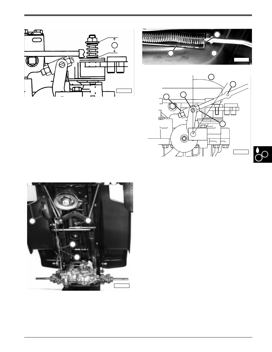
BRAKE SPRING ADJUSTMENT
1. Unlock park brake lever (B) and release brake
pedal (A).
2. Measure distance between centers of brake lever
hole (G) and brake rod hole (I), distance should be
85 mm (3.35 in.).
3. If not, gradually adjust jam nuts (F and J) until
specified measurement is obtained.
4. Depress pedal (A) and lock park brake (B).
5. Measure distance between end of compression
spring bracket (C) and front edge of brake rod stop
tabs (D), gap should have a minimum distance
of 2 mm (0.08 in.).
6. Check brake rod compression spring (E), it should
not be completely compressed, as shown, when
park brake is locked. A slight air gap should be
visible between the coils when proper adjustment
is reached.
7. Recycle park brake a few times and remeasure
distances each time until specified measurements
are obtained.
8. Brake lever travel (H) should not exceed 30°, if it
does measure brake components individually.
Specifications:
Brake lever hole-to-brake rod hole
. . . . . . . . . . . . . . . . . . . . . . . . . . . . 85 mm (3.35 in.)
Spring bracket-to-stop tabs
(minimum). . . . . . . . . . . . . . . . . . . . 2 mm (0.08 in.)
Brake lever travel (maximum) . . . . . . . . . . . . . . . . 30°
E
M58276
M58258
D
C
B
A
M42596
C
D
E
M58273
H
J
I
F
G