John Deere stx38 User Manual
Page 138
4 - 54
3/21/97
CIRCUIT OPERATION AND DIAGNOSIS
ELECTRICAL
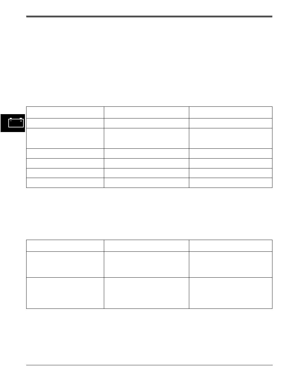
PTO CIRCUIT DIAGNOSIS POINTS
STX30 & STX38 (SN —210000)
Test Conditions:
• Transaxle in neutral
• Key switch in run position
• Park brake engaged
• Meter negative (-) lead on battery negative (-)
terminal
• PTO switch ON (engaged)
• Meter positive (+) lead on numbered test point
Test/Check Point
Normal
If Not Normal
1. Battery positive terminal.
11.8—13.2 volts
Test battery
2. Key switch terminal B.
Battery voltage
Check battery cable connection,
fusible link or circuit breaker and
200/210 red wires.
3. Key switch terminal A.
Battery voltage
Replace key switch.
4. PTO switch—yel wire.
Battery voltage
Test 510 yellow wire.
5. PTO switch—blue wire.
Battery voltage
Replace PTO switch.
6. PTO clutch—yel wire.
Battery voltage
Test 750 blue wire.
Test Conditions:
• Key switch in off position
Test/Check Point
Normal
If Not Normal
7. PTO clutch—blk wire.
Maximum 0.1 ohms
Check PTO clutch ground circuit—
120 blk wire, engine, frame, and
battery negative cable ground
connection.
8. PTO clutch
PTO clutch air gap
Warner—0.38—0.64 mm (0.015—
0.025 in.)
Ogura—0.30—0.51 mm (0.012—
0.020 in.)
Adjust air gap to 0.51 mm (0.020
in.) .
If air gap OK, replace PTO clutch.