Ignition module test, Seat switch test – John Deere stx38 User Manual
Page 152
4 - 68
3/21/97
TESTS AND ADJUSTMENTS
ELECTRICAL
IGNITION MODULE TEST
Reason:
To determine condition of ignition module windings.
Equipment:
• Ohmmeter
Procedure:
1. Put transaxle in neutral. Put key switch in off
position.
2. Remove spark plug cap from spark plug wire.
3. Disconnect primary lead wire.
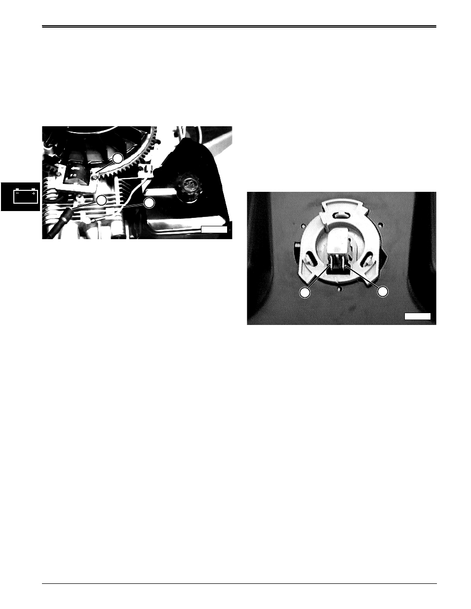
4. Measure resistance between primary lead (B) and
core (A). Reverse meter leads and check
resistance again.
5. Measure resistance between spark plug lead (C)
and core (A).
Specifications:
Primary lead and core resistance:
One direction . . . . . . . . . . . . . . . . . . . 5—1000 ohms
Other direction (Minimum) . . . . . . . . . . . 30 K ohms
Spark plug lead and core
resistance . . . . . . . . . . . . . . . . .7.9—10.85 K ohms
Results:
• If resistance does not meet specifications, replace
the ignition module.
SEAT SWITCH TEST
Reason:
To ensure proper operation of seat switch.
Equipment:
• Ohmmeter
Procedure:
1. Park machine on level surface and turn key switch
OFF.
2. Shift lever in NEUTRAL and park brake LOCKED.
3. Disconnect harness connector from seat switch.
4. Check continuity across switch terminals (A) and (B).
Results:
• There should BE continuity between terminals (A
and B) when seat is RELEASED,
• There should NOT BE continuity between terminals
(A and B) when plunger is DEPRESSED.
• If continuity is NOT correct, replace switch.
NOTE: The seat switch connector has an interlock
spring which shorts the 3 wires together when
it is removed from the seat switch terminals.
Check that spring mechanism is releasing
properly when the center tab is depressed.
M55638
B
A
C
B
A
M55816