John Deere stx38 User Manual
Page 223
3/20/97
5 - 59
POWER TRAIN
REPAIR
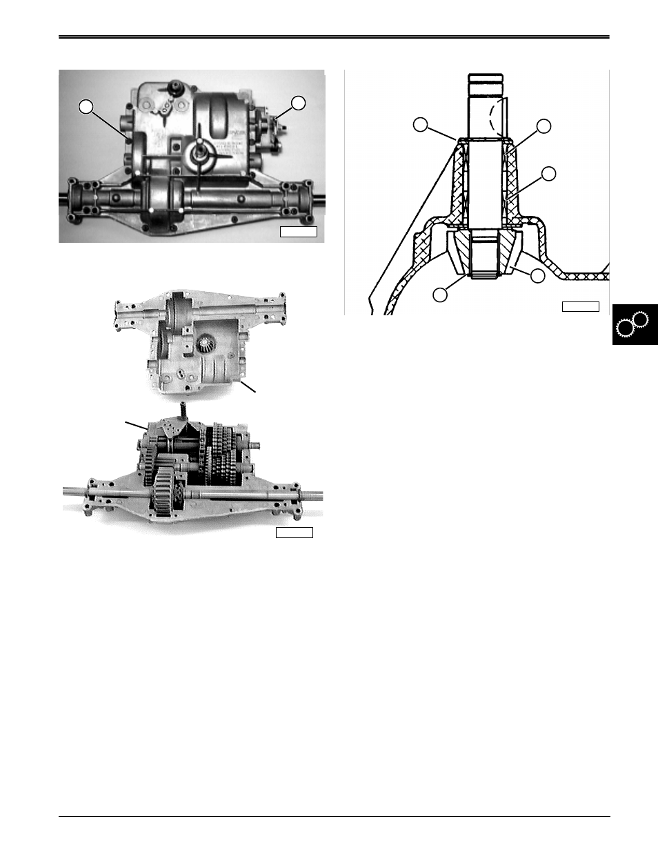
Separate Transaxle Housing Case Halves:
1. Remove all sixteen transaxle housing socket head
screws (B)—brake assembly (A) should be
removed already, see previous procedure.
2. Carefully separate transaxle housing into upper and
lower case halves.
3. Inspect overall condition of components without
removing any of them. Visually target worn or
damaged parts for replacement.
4. Remove most of the grease without removing any
components.
Inspect Input Shaft/Pinion Gear Assembly:
1. Visually check overall condition of assembly,
including the key and keyway, and the drive
sheave hub keyway as well.
2. Check condition of pinion gear (D)—look for wear,
pitting, broken teeth, etc.
3. Grasp the input shaft and try to rock it left or right
inside case housing. If movement is noticeable,
needle bearings (B and C) inside diameters will
need to be measured once shaft is removed.
4. Use a feeler gauge to measure “go/no go” air gap
between pinion gear (D) and snap ring (E):
• “GO” air gap should be 0.25 mm (0.010 in.) or less
• “NO GO” measurement is anything greater.
5. If measurement results in a “NO GO” reading, shim
thickness (A) needs to be changed or worn
components must be replaced.
B
M42312
A
M42318
Upper Case
Half
Lower Case
Half
M42525
E
D
B
C
A