John Deere stx38 User Manual
Page 112
4 - 28
3/21/97
CIRCUIT OPERATION AND DIAGNOSIS
ELECTRICAL
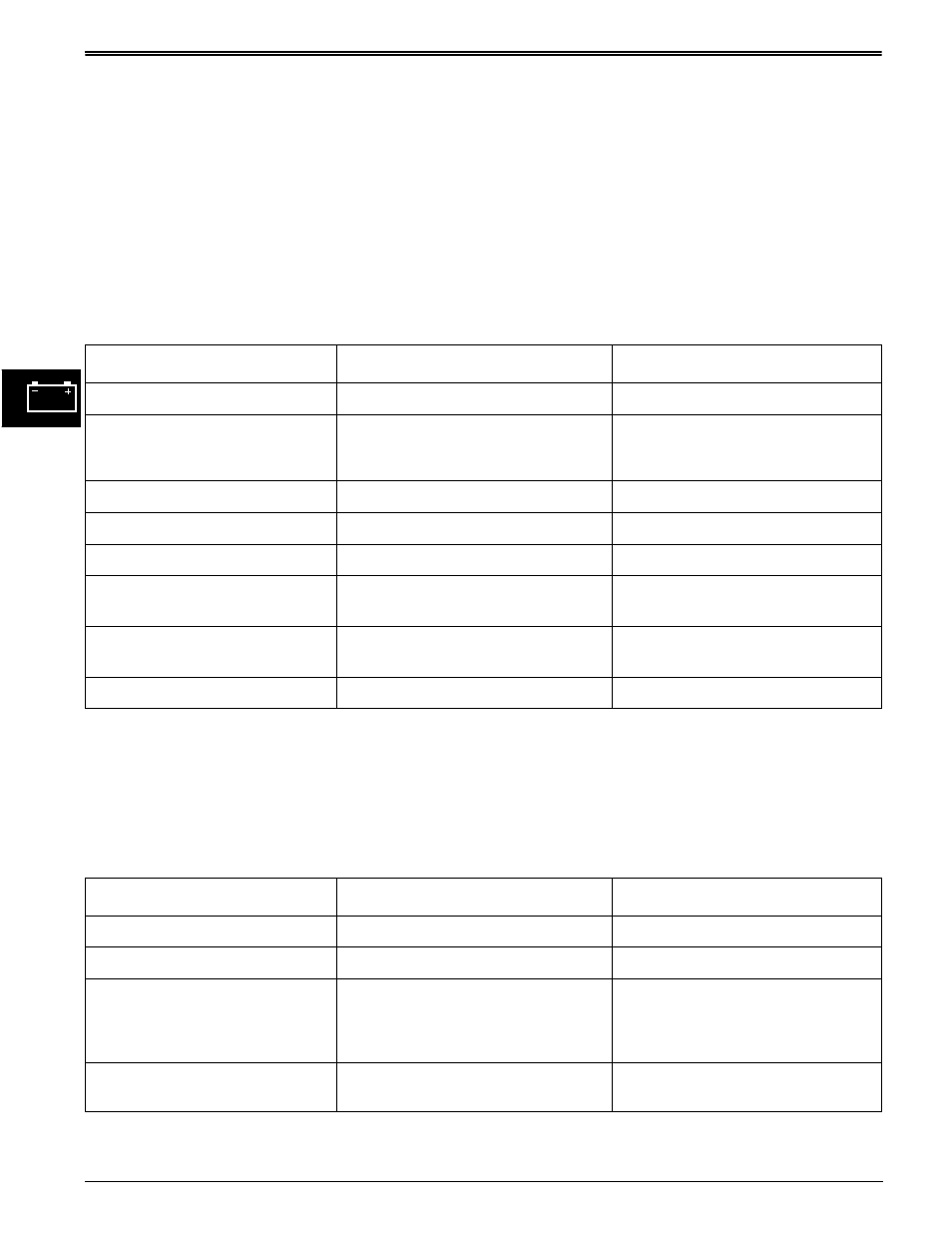
CRANKING CIRCUIT DIAGNOSIS
STX30 & STX38 (SN —210000)
Test Conditions:
• Transaxle in neutral
• Key switch in run position
• Park brake engaged
• Meter negative (-) lead on battery negative (-)
terminal
• PTO switch disengaged
• Meter positive (+) lead on numbered test point
Test/Check Point
Normal
If Not Normal
1. Battery positive terminal.
11.8—13.2
Test battery.
2. Key switch terminal B.
Battery voltage
Check battery cable connection,
fusible link or circuit breaker and
210/201 red wire.
3. Key switch terminal A.
Battery voltage
Replace key switch.
4. PTO switch yellow wire.
Battery voltage
Test 510 yellow wire.
5. PTO switch purple wire.
Battery voltage
Replace PTO switch.
6. Neutral start switch 720 pur
wire.
Battery voltage
Test purple wire.
7. Neutral start switch 710 pur
wire.
Battery voltage
Replace neutral start switch.
8. Key switch terminal S1.
Battery voltage
Test purple wire.
Test Conditions:
• Key switch in start position
Test/Check Point
Normal
If Not Normal
9. Key switch terminal S2.
Battery voltage
Replace key switch.
10. Starter solenoid terminal S.
Battery voltage
Test purple wire.
11. Starter solenoid ground
terminal.
Greater than 0—less than 0.2 volts.
Greater than 0.2 volts—check
starter solenoid ground circuit and
130 Blk wire.
0.0 volts—Replace starter solenoid.
12. Starting motor
Battery voltage
Check red wire, if OK test starting
motor.