John Deere stx38 User Manual
Page 228
5 - 64
3/20/97
REPAIR
POWER TRAIN
TRANSAXLE ASSEMBLY—
STX38 (SN 210001— ) & STX46
NOTE: STX38 (SN 301383— ) transaxle differs
slightly from STX38 (SN 210001—301382)
and STX46 transaxle.
IMPORTANT: Coat lightly all mating surfaces,
except seal surfaces, with SAE 30 weight oil
before assembly. Pay close attention to proper
order and orientation of all components. Also, it
is recommended that you use a calliper to
ensure the correct shim, spacer, or washers are
installed correctly.
Assemble Differential/Axle Shafts Assembly:
1. Assemble left-hand, short axle (A) as shown with
splined, beveled gear facing the ring gear.
2. Assemble right-hand, long axle (D) as shown with
splined, beveled gear facing the ring gear and
shim washers (B) assembled in combination of
thicknesses to obtain specified air gap (see
Inspect Differential/Axle Shafts Assembly).
3. Assemble internal shaft (C) as shown with beveled
gears facing each other.
4. Install internal shaft assembly in slots of ring gear
and push beveled gears away from each other so
they are ready to mesh with both axle beveled
gears.
5. Install axle shafts so beveled gears (E) mesh with
differential internal shaft beveled gears.
6. Keep inward pressure on both axles as you install
differential assembly in lower case housing.
7. Measure air gap between shim washers (F) and
side of housing (H). If air gap meets specification
(see Inspect Differential/Axle Shafts Assembly), go
to next step. If air gap does not meet specification,
remove right axle shaft and add other shim washer
combinations until air gap in within specification.
8. Carefully install new axle shaft seals (G and I) and
seat them in their lower case housing grooves.
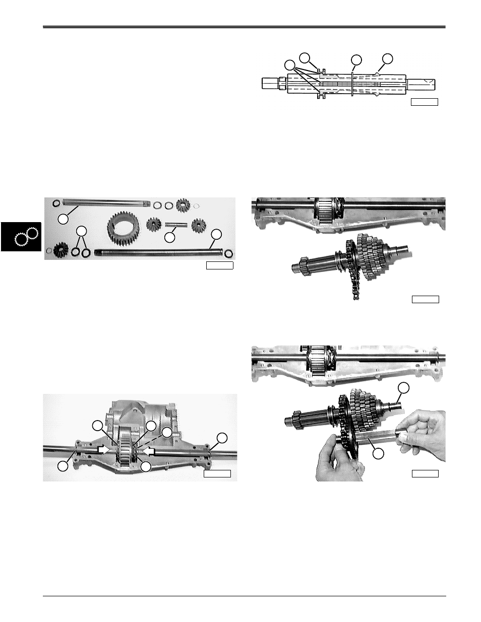
Assemble Drive/Intermediate Shaft Assemblies:
1. Install retaining ring (C) in intermediate shaft
groove.
2. Install four keys in grooves of intermediate shaft
and hold them so internal shift collar anchors (A)
will seat in internal groove of collar (B) as it is
installed on the shaft.
3. Slide shift collar and keys against retaining ring (C)
and compress locking ramps/lugs (D) to clear
retaining ring.
4. Install remaining intermediate shaft components in
their proper order and orientation (reference top
two rows of components in photo on opposite
page).
5. Install drive shaft components one at a time from
left-to-right (reference bottom row of components
in photo on opposite page). Long flange of small
sprocket (J) faces bevel drive gear.
6. Shim washer(s) (E) for intermediate shaft (F) are
found in Shim Kit.
7. Shim washer(s) (H) for drive shaft (I) are found in
Shim Kit.
8. Install new intermediate shaft seal (G) with open lip
facing inside.
M42493
C
B
D
A
M42492
E
E
G
F
H
I
M42526
B
C
D
A
M42498
M42499
F
I