Brake pedal/park brake switch tests, Brake switch adjustment – John Deere stx38 User Manual
Page 153
3/21/97
4 - 69
ELECTRICAL
TESTS AND ADJUSTMENTS
BRAKE PEDAL/PARK BRAKE
SWITCH TESTS
Reason:
To make sure the brake pedal switch operates
properly.
Equipment:
• Ohmmeter
Procedure:
1. Park machine on level surface and turn key switch
OFF.
2. Shift lever in NEUTRAL and park brake LOCKED.
3. Disconnect harness connector from brake switch.
4. Check continuity.
Results:
• there should BE continuity between terminals (B
and C) when plunger is RELEASED,
• there should NOT BE continuity between terminals
(B and C) when plunger is DEPRESSED.
• there should NOT BE continuity between terminals
(A and D) when plunger is RELEASED,
• there should BE continuity between terminals (A
and D) when plunger is DEPRESSED.
• If continuity is NOT correct, replace switch.
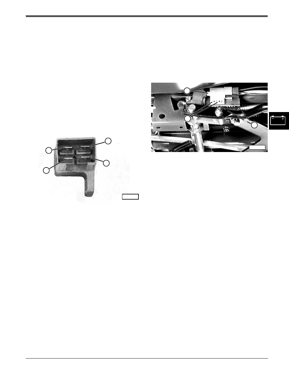
BRAKE SWITCH ADJUSTMENT
Reason:
To ensure proper that engine starts only when brake
fully applied.
Procedure:
1. Depress brake pedal and set park brake.
2. Check condition of both mounting rivets (C). If not
tight, damaged, or improperly installed, they could
affect adjustment and function of start and safety
circuits. If rivets are bad, go to Step 3; if rivets are
good, go to Step 4.
3. Disconnect harness connector and remove switch
assembly to bench vise. Remove rivets, as
necessary, using a 4.76 mm (3/16 in.) drill bit and
replace with 4.75 x 14.61 mm (0.187 x 0.575 in.)
aluminum pop rivets (M67899). Loosely install
switch and solidly connect harness connector.
4. Loosen switch bracket hardware (B).
5. Move switch until plunger (A) is about 3 mm (1/8 in.)
from bottoming.
6. Check that switch does not bottom when brake
pedal fully depressed. Increase clearance if
needed.
7. Tighten bracket hardware.
8. Check switch operation.
• Engine should NOT turn over or start when brake
pedal is NOT depressed.
• Engine should turn over and start when brake pedal
is fully depressed.
• If operation is not correct, test switch.
M56409
C
A
D
B
M55800
B
A
C