John Deere stx38 User Manual
Page 264
6 - 32
3/21/97
REPAIR
HYDROSTATIC POWER TRAIN
Remove Reservoir Cover—
NOTE: If there is no damage to cover or upper case
housing, you need not remove cover because
there are no components inside the reservoir.
1. Remove four cap screws (A) to remove reservoir
cover.
2. Inspect cover for cracks or holes, replace as
necessary.
3. If cover is in good condition and to be reused, clean
off all gasket residue and wipe clean, then set
cover and four cap screws aside for final
assembly.
Remove Breather Valve Assembly—
1. Pull breather valve assembly from reservoir cover.
2. Inspect condition of breather valve assembly,
replace as necessary.
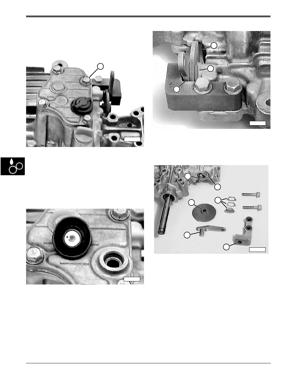
Remove Brake Assembly—
1. First, inspect brake assembly for wear or damage:
• check for brake disc contact points at case points (1
and 2),
• check for brake lever contact point at mounting
bracket edge (3). If contact is detected, replace
lever, disc, and friction puck as a set.
2. Remove two cap screws to remove brake
assembly.
3. Inspect intermediate shaft brake splines (A) and
brake disc splines (B) for chips, rust, and broken
teeth. Replace as necessary.
4. Inspect mating surfaces of brake lever shaft (C) and
mounting hole (D) for scoring, pitting, and wear.
Replace as necessary.
5. Inspect mating surfaces of case recess (F) and
friction puck and shims (E) for rust. Clean or
replace as necessary.
M58205
A
M58206
M58281
1
2
3
M58208
A
B
D
C
F
E