Shift linkage adjustment – John Deere stx38 User Manual
Page 201
3/21/97
5 - 37
POWER TRAIN
TESTS AND ADJUSTMENTS
SHIFT LINKAGE ADJUSTMENT
Reason:
To ensure shift lever obtains all shift positions and that
neutral position does not allow transaxle to creep.
Conditions:
• Safely raise rear wheels 51 mm (2 in.) off surface
and block front wheels (front and rear).
• Shift lever in neutral.
• Park brake off.
Procedure:
1. Check that shift linkage hardware (A and B) is in
good condition and tight.
2. Start and run engine at fast idle.
3. Check that transaxle does not creep (axle rotation
while shift lever is in neutral position and clutch/
brake pedal released).
4. If transaxle creeps, move shift lever (D) slightly
inside neutral slot (C) of shift quadrant until creep
motion stops.
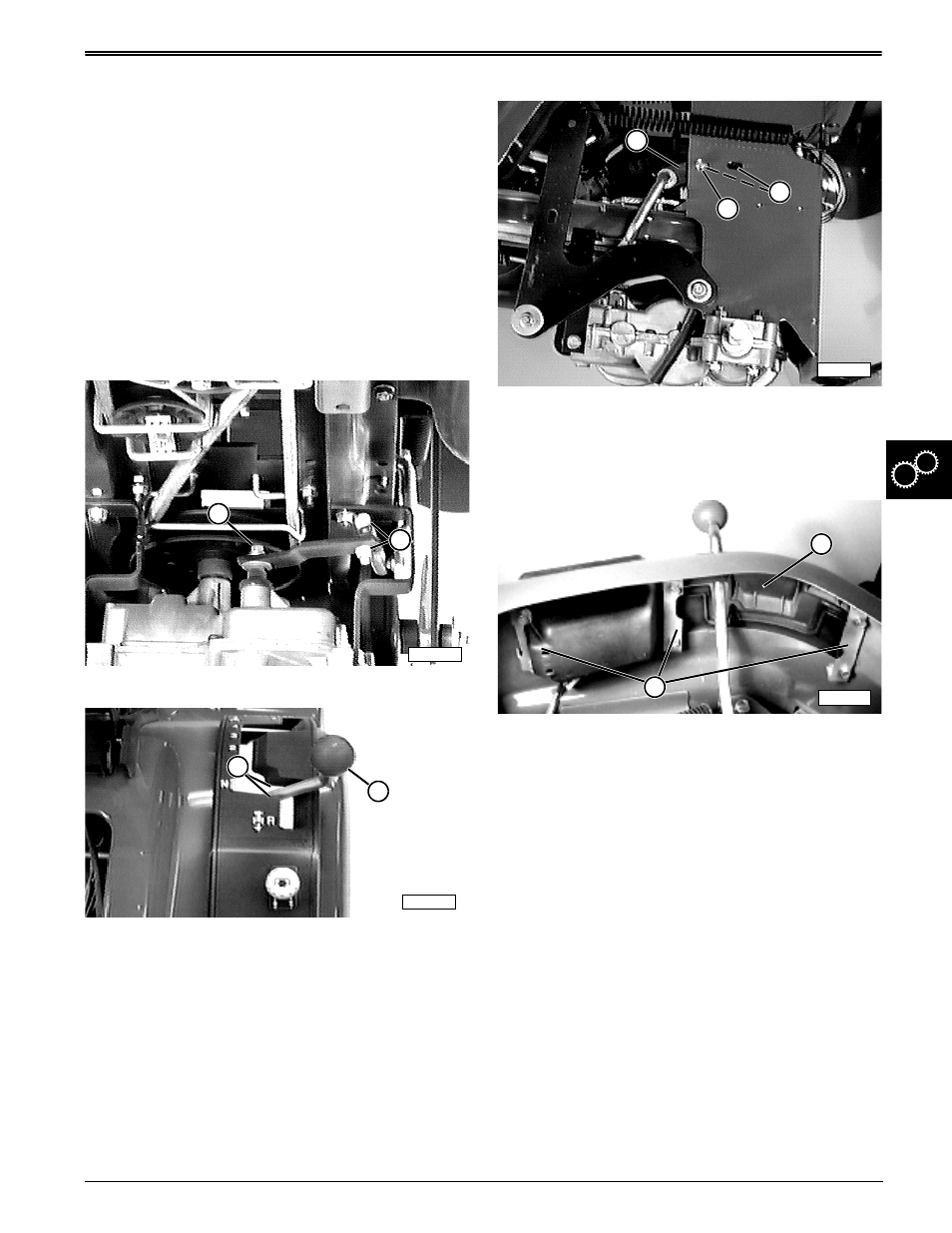
5. If shift lever is moved and creep motion does not
stop, turn engine off and loosen left side lock nut
(E) (left wheel removed for clarity purposes only).
6. Start and run engine at fast idle while you slide left
side bracket (F) forward or rearward in slots (G)
until creep motion stops. Tighten nut.
7. If left side bracket adjustment (Step #6) does not
stop creep motion and shift quadrant (H) does not
allow enough shift lever movement to stop creep
motion, loosen three mounting brackets (I).
8. Adjust quadrant forward or rearward until transaxle
does not creep with shift lever in the center of the
neutral position and clutch/brake pedal released.
9. Stop engine, hold quadrant in place, and tighten
three mounting brackets (I).
10. Lower tractor to surface and remove blocks.
Results:
• Test drive tractor to ensure all forward and reverse
gears are obtained and that transaxle does not
creep in neutral position.
• If adjustments are not satisfactory, repeat
procedure until proper results are obtained.
• If adjustments are still not satisfactory, internal
transaxle repair is needed.
M42590
A
B
M55808
D
C
M42535
E
F
G
M55803
I
H