John Deere stx38 User Manual
Page 212
5 - 48
3/21/97
REPAIR
POWER TRAIN
TRANSAXLE—REMOVAL/
INSTALLATION
STX30 (SN 135159—160758) &
STX38 (SN 139615—185586)
(PEERLESS MODELS 915-012A &
915-012B)
IMPORTANT: Early models used several versions
of transaxle. The 915 model is used in the 1992
production models and has a completely
different shape then the older models.
Removal
1. Remove ignition key and disconnect spark plug
wire.
2. Raise rear of tractor and support safely.
3. Remove rear wheels.
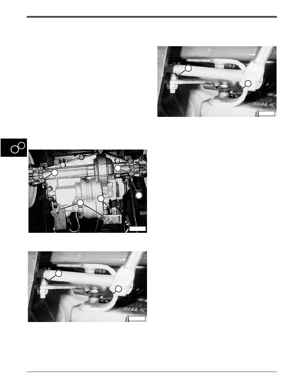
4. Loosen transaxle mounting cap screws (A) and
frame-to-bracket nuts (B) (Right-hand shown).
5. Disconnect brake linkage (C).
6. Disconnect shift linkage (D), and neutral switch (E).
7. Depress clutch pedal and remove drive belt from
transaxle drive sheave.
8. Remove mounting cap screws and remove
transaxle.
Installation
1. Install transaxle leaving hardware loose.
2. Install drive belt.
3. Connect brake linkage (C)—see depiction step 4,
shift linkage (D) and neutral switch (E).
4. Tighten mounting cap screws and install rear
wheels.
Specifications:
Transaxle Mounting Cap Screws to Hanger
Bracket (Front) . . . . . . . . . . . . 15 N•m (132 lb-in.)
Transaxle Mounting Cap Screws to
Frame (Rear) . . . 20.3—47.4 N•m (180—420 lb-in.)
M42175
A
A
C
B
A
M85844
E
D
M85844
E
D