John Deere stx38 User Manual
Page 266
6 - 34
3/21/97
REPAIR
HYDROSTATIC POWER TRAIN
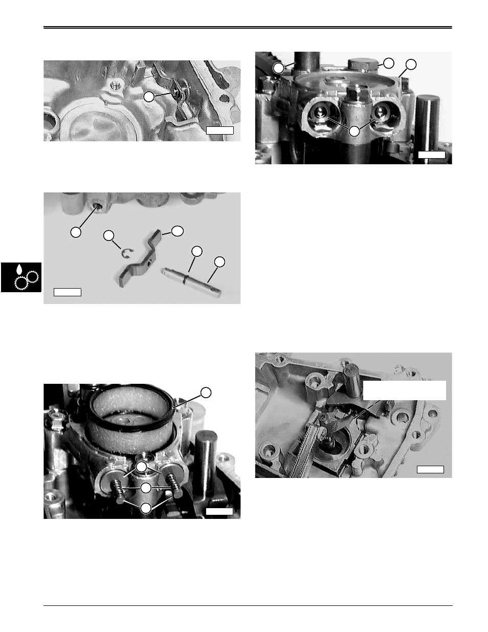
Disassemble Transport (Free-Wheeling)
Assembly–
NOTE: Inspect transport actuating bracket and pin
assembly (A) for wear or leakage to outside. If
assembly is in good condition, just set lower
case half aside for final assembly.
1. If wear or leakage is detected, remove e-ring (C),
actuating bracket (D), and pin (F).
2. Remove and discard o-ring (E). Replace it with new
o-ring every time assembly is removed or leaking.
3. Inspect pin (F) and lower case bore (B) for pitting,
scoring, or rust. Replace as necessary.
4. Inspect e-ring (C) and bracket (D) for wear or
deformity. Replace as necessary.
K-50 Version Shown
5. Remove and discard filter (G). Replace it with a
new filter every time case halves are separated.
6. Remove and inspect push pins (J), springs (I), and
push pin guides (H). Replace as necessary.
7. Inspect transport bypass relief valve body and balls
(N) for pitting, scoring, discoloration, or damage.
8. If any detected, install brake disc on motor drive
shaft splines and hold shop cloth over valve bores
to catch valve bodies.
9. Turn brake disc clockwise to force one of valve
assemblies (N) from center block (M), then turn
brake disc counterclockwise to force other valve
assembly from center block.
10. If valve assemblies do not dislodge, remove plug
(L) and bleed port connector (K) and try using
compressed air to dislodge valve assemblies.
11. If valve assemblies still remain lodged, depress
check balls with extractor tool(s) to grab onto valve
body and pull them from center block and discard
valve bodies.
12. Check bores, if damaged—replace center block.
Disassemble Shifter Shaft Assembly—
(Pump, motor, and center block removed for clarity)
M55843
A
B
C
D
E
F
M55839
M58212
G
H
I
J
M58211
N
M
L
K
M58241
Maximum Air Gap
0.15 mm (0.0059 in.)