Transaxle case halves— assembly, Brake assembly— installation – John Deere stx38 User Manual
Page 278
6 - 46
3/21/97
REPAIR
HYDROSTATIC POWER TRAIN
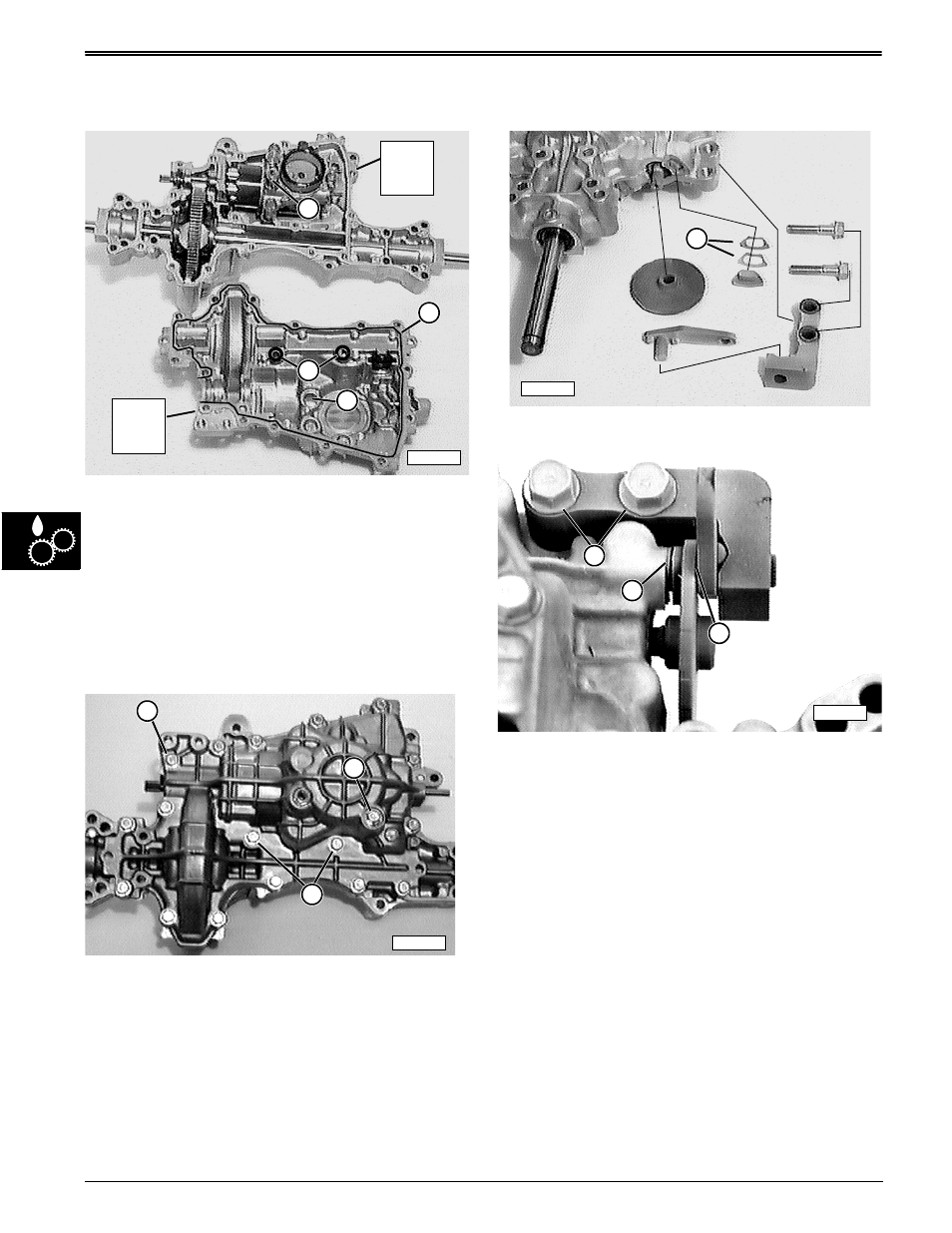
TRANSAXLE CASE HALVES—
ASSEMBLY
K-50 Version Shown
1. Make sure mating surfaces of transaxle case
halves are clean.
2. Apply a solid bead (B) of John Deere Form-In-Place
Silicone Gasket Sealant around lower case half.
Be sure to stay to the inside of the mounting holes.
3. Be sure to apply a solid bead around two inner
holes (D).
4. Align hole (C) with bleed port stack (A) and firmly
push lower case half onto upper case half.
5. Align all 17 case halves holes.
6. Install 17 cap screws (E) finger tight initially and
then tighten from center-to-outside in a crossing
pattern, beginning with two cap screws (G).
Tighten 17 cap screws to specifications.
7. Install new o-ring on drain plug (F) and tighten it to
specification.
Specifications:
New upper case . . . . . 27—31 N•m (243—278 lb-in.)
Used upper case . . . . 23—27 N•m (200—243 lb-in.)
Drain plug . . . . . . . . . . 20—24 N•m (174—217 lb-in.)
BRAKE ASSEMBLY—
INSTALLATION
Brake Pad Adjustment
1. Install brake components to transaxle and, using
friction puck shims (B), adjust air gap (C) between
brake lever and brake disc (use feeler gauge) to
specification.
2. Tighten cap screws (A) to specification.
3. Brakes should hold tractor on 17° slope and not
drag when tractor is level and pushed in neutral.
Specifications:
Brake air gap . . . . . . . . . . . . . . 0.254 mm (0.010 in.)
Brake cap screws. . . . 44—59 N•m (391—521 lb-in.)
M55842
B
D
C
A
Upper
Case
Half
Lower
Case
Half
M58210
F
G
E
M58208
B
A
B
C
M58207