Cooper Instruments & Systems DFI INFINITY Digital Force Indicator/Controller User Manual
Page 9
JUMPER
RS485
HALF DUPLEX
RS485
FULL DUPLEX
(CLOSE FOR TERMINAL
RESISTOR)
S3-B CLOSE
OPEN
S3-C
(CLOSE FOR TERMINAL
RESISTOR)
* *
S3-D CLOSE
OPEN
S3-E
(CLOSE FOR RTS
TRUE)
OPEN OPEN
S4
(CLOSE FOR
CONTINUOUS MODE)
* *
Note: * means optional, select as required.
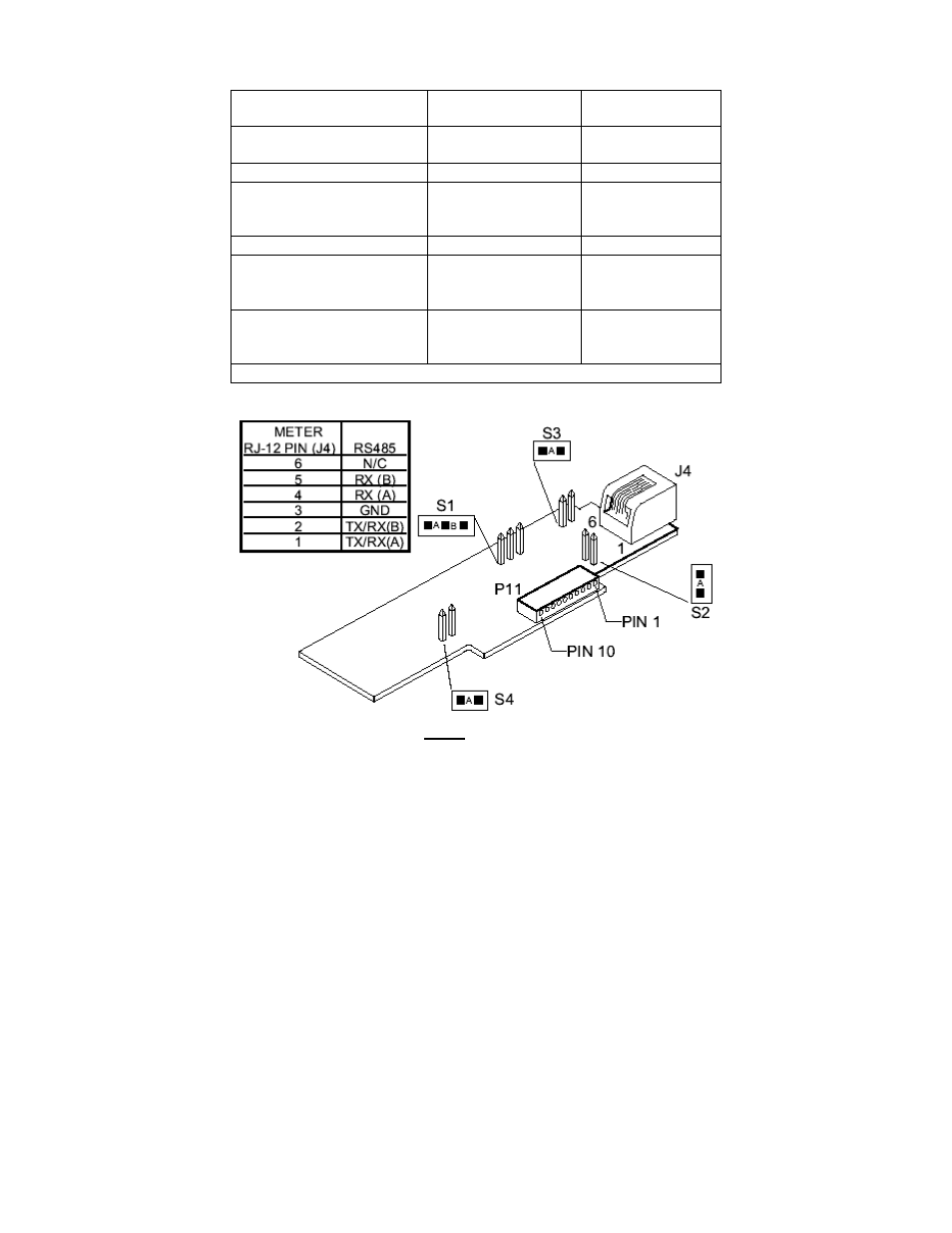
Figure 2-5B. Older RS-485 Option Board
Figure 2-5B shows the card outline and the pin designators for the connectors.
There are 4 jumper-selected features.
Putting a jumper in S1-A adjust for HALF DUPLEX (see Definitions in Section 4)
A jumper in S1-B allows for FULL DUPLEX.
A jumper in S2 adds an impedance-matching 121 ohms across the HALF DUPLEX lines.
A jumper in S3 to impedance-match the other pair of wires, for FULL DUPLEX.
For normal RS-485 operation: remove S4.
For continuous transmission: install S4 and set BUS format menu item as follows:
BUS.4=0
BUS.5=0
BUS.7=0
CF 125 INFINITY SC GUIDE
5
M1519/N/0605