Selects, Configuration, 16serial communications configuration \(“ser – Cooper Instruments & Systems DFI INFINITY Digital Force Indicator/Controller User Manual
Page 49: Serial communications configuration (“ser.cnf”)
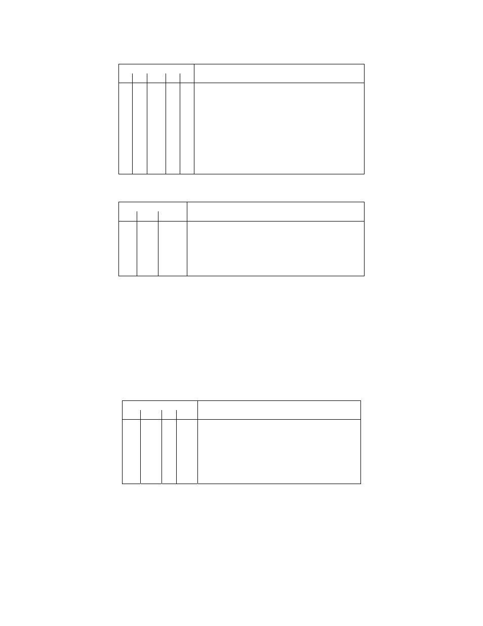
Table 10.27. Output Configuration (“OUT.CNF”) Bits 4, 3, 2, 1, and 0
BIT NUMBERS
4 3 2 1 0
SELECTS
x x x
x 0 Analog output disabled
x x x
x 1 Analog output enabled
x x x
0 x 0-10 V output
x x x
1 x 0-20 mA output
x x 0 x x Parallel
BCD
disabled
x x 1 x x Parallel
BCD
enabled
x 0 x
x x BCD driven by display value
x 1 x
x x BCD driven by PEAK value
0 x x
x x Large or desktop printers
1 x x x x Panel
printers
Table 10.28. Output Configuration (“OUT.CNF”) Bits 7, 6, and 5
BIT NUMBER
7 6 5
CONFIGURATION
0
0
0
No display flashing when any setpoint active
0
0
1
Display flash for SP 1
0
1
0
Display flash for SP 2
0
1
1
Display flash for SP 3
1
0
0
Display flash for SP 4
1
0
1
Display flashes for any setpoint
“P” or “G” commands can exchange this status with the RAM, while “W” or “R” commands can exchange with
the nonvolatile EEPROM (where a subsequent “RESET2” command moves these data into RAM as well).
EXAMPLE: If the computer sends “*15W16D
flash for SP 2, that it is to drive a panel printer, that both 0-10 V Analog Output and Parallel BCD are to be
driven, and with BCD showing the PEAK values.
10.16 Serial Communications Configuration (“SER.CNF”)
This “18” command suffix has byte (2 nibbles, in two characters) of data. (This information may already have
been entered by pushbutton or diskette. It resides only in EEPROM, so that only “R/W” command letters apply.)
Table 10.29. Serial Configuration (“SER.CNF”) Bits 3, 2, 1, and 0
BIT NUMBER
3 2 1 0
SELECTS
0
0
0 0
Baud rate = 300
0
0
0 1
Baud rate = 600
0
0
1 0
Baud rate = 1200
0
0
1 1
Baud rate = 2400
0
1
0 0
Baud rate = 4800
0
1
0 1
Baud rate = 9600
0
1
1 0
Baud rate = 19200
CF 125 INFINITY SC GUIDE
45
M1519/N/0605