1pushbutton communications setup, Pushbutton communications setup – Cooper Instruments & Systems DFI INFINITY Digital Force Indicator/Controller User Manual
Page 11
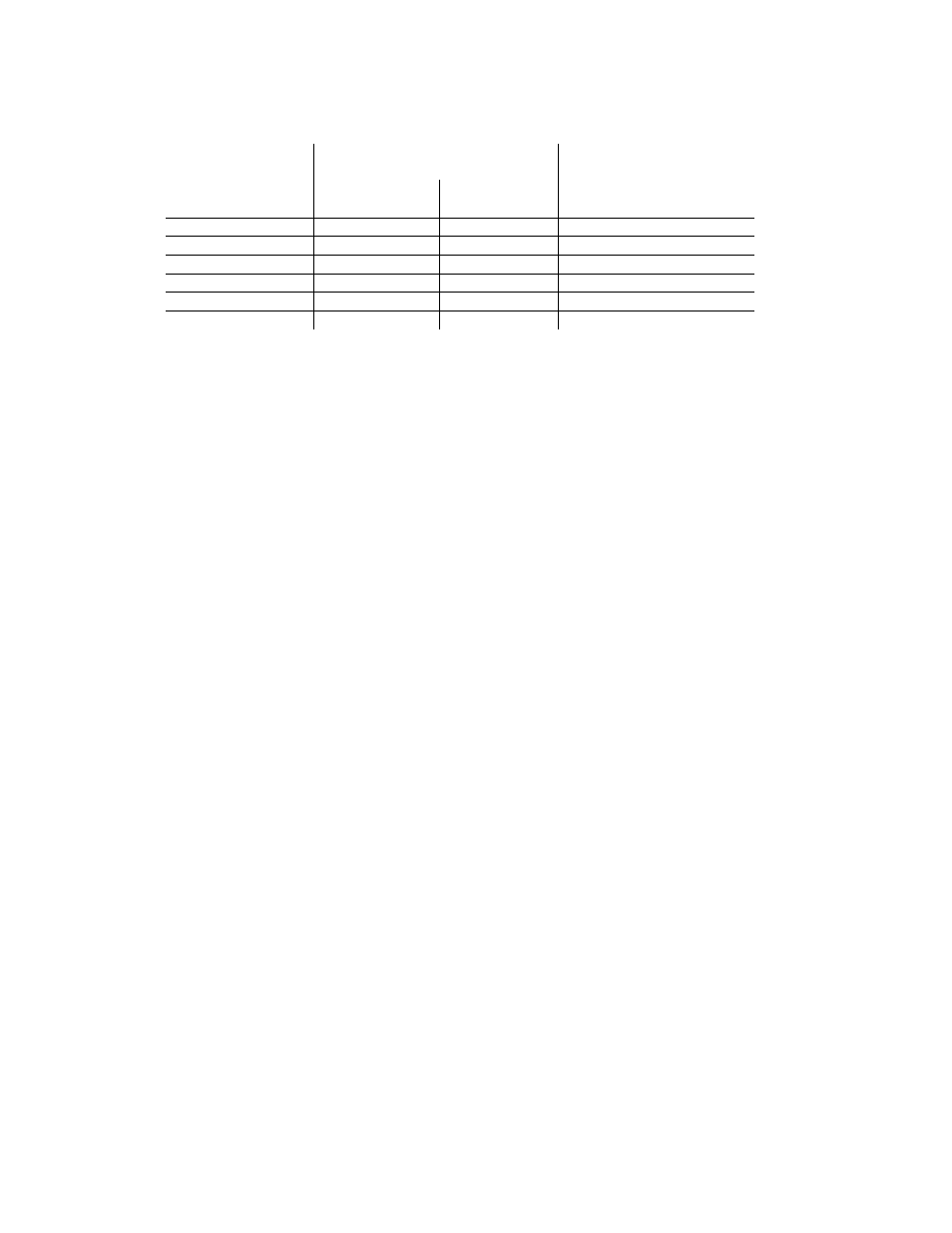
Table 2.4. Full-Duplex Hookup to the Computer
METER (DCE)
RJ-12
NEW OLDER
PIN SIGNAL/
FUNCTION
RS-485 RS-485
BD
COMPUTER (DTE)
D9/D25
+TX
1
1
(SEE MFG DWG)
-TX
3
2
(SEE MFG DWG)
+RX
2
4
(SEE MFG DWG)
-RX
4
5
(SEE MFG DWG)
N/C or RTN
-
3
(SEE MFG DWG)
N/C - 6
Both HALF DUPLEX (Figure 2-6) and FULL DUPLEX RS-485 (Figure 2-7) communications require a 6-wire RJ-
12 plug to be connected to the RJ-12 jack at the rear of the meter.
Unlike RS-232, there presently is no established standard D9 or D25 connector pin-out for RS-485; refer to your
computer or controller manual to insure the right cable connections.
NOTE: If communications with your meter has failed, it is recommended that you check for the receive portion of
the RS-485 board on DTE (computer). These lines should be pulled up for +RX and pulled down for –RX with
resistors with a resistance value from 330 ohms 1k ohms.
3.
USING THE CONFIGURATION AND COMMUNICATIONS DISKETTES
NOTE: Configuration and Communications Diskettes are furnished only with the Process, Strain, Temperature,
and Universal meters. These diskettes are not offered with the rate meter/totalizers, or batch controllers.
The diskettes provide computer-screen prompts for communication setup, control of your meter, and data
acquisition.
Although the diskette program provides for selection of many meter features, it is not designed to assist the
generation of custom-designed control and data acquisition programs: that information is given starting with
Section 4, covering the protocol, coding and format for all of the meter commands and responses.
3.1
Pushbutton Communications Setup
Although the diskette program can automatically search for the baud rate, parity and stop-bit settings that have
been set into the meter, the search is shorter if these are set to factory-preset values via the front-panel
pushbuttons.
To enter these values, first unlock the communications bits by setting all “L4 CNF” bits to equal “0”.
Next, press the ‘MENU’ button until “BAUD” is displayed, then press the ‘MIN’ button to see the previously-set
value of the baud rate (nominally “9600”). Press the ‘MAX’ button to rotate around to this nominal value, unless
some other baud rate has been selected.
Now press the ‘MENU’ button to store this choice and display “SERCNF”. Press the ‘MIN’ button to see
“SER.1=0” for no parity, “SER.1=1” for odd parity (the factory preset setting), or “SER.1=2” for even parity. If
your computer uses different parity, set the appropriate choice by pressing the ‘MAX’ button, and advance to
“SER.2” by pressing the ‘MIN’ button.
Setting “SER.2=0” picks the factory preset value of one stop bit; setting “SER.2=1” selects two stop bits.
(Note: the combination of no parity and single stop bit has fewer bits than the chosen standard. Therefore, the
meter automatically selects two stop bits when you select no parity.)
CF 125 INFINITY SC GUIDE
7
M1519/N/0605