Cooper Instruments & Systems DFI INFINITY Digital Force Indicator/Controller User Manual
Page 7
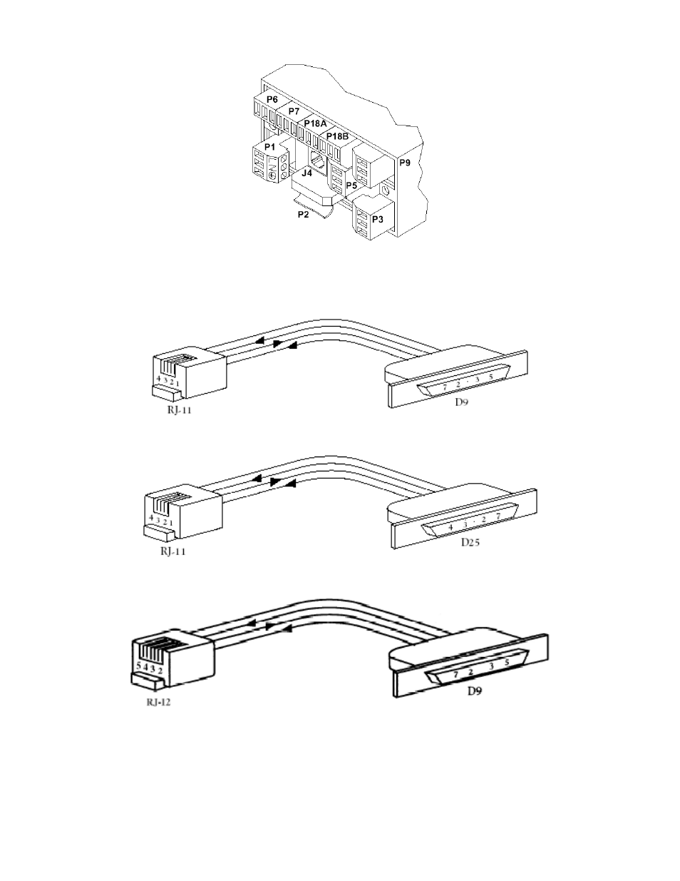
Figure 2-3. Rear of Meter with J4 Connection
Figures 2-4A and Figure 2-4B show the four-wire RS-232 connections between the host computer/controller
using either a 9-pin or 25-pin “D” connector and the meter (point-to-point full duplex, with RTS handshake).
Figure 2-4A. RJ-11 to D9 Connector
Figure 2-4B. RJ-11 to D25 Connector
Figure 2-4C. RJ-12 to D9 Connector
Table 2.1 shows the pin connection assignments between the RS-232 connection on the meter and the 9-pin or
25-pin “D” connectors of your computer.
CF 125 INFINITY SC GUIDE
3
M1519/N/0605