Bit pattern, Sign and decimal point, 25block read or write – Cooper Instruments & Systems DFI INFINITY Digital Force Indicator/Controller User Manual
Page 54: Block read or write
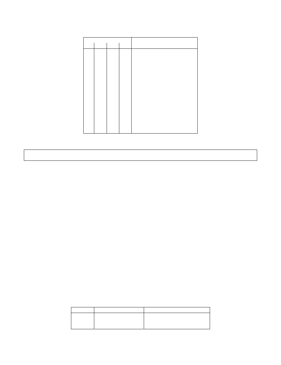
Table 10.37. Setpoint Values, Bits 23, 22, 21, and 20
BIT PATTERN
23 22 21 20
SIGN AND DECIMAL POINT
0 0 0 0
0 0
+FFFFFF.
0 0 1 0 +FFFFF.F
0 0 1 1 +FFFF.FF
0 1 0 0
1 0 1 +FF.FFFF
0 1 1 0 +F.FFFFF
0 1 1 1 Not
used
1 0 0 0 Not
used
1 0 0 1 -FFFFFF.
1 0 1 0 -FFFFF.F
0 1
-FFFF.FF
1 0 0 -FFF.FFF
1 0 1 -FF.FFFF
1 1 1 0 -F.FFFFF
1 1 1 1 Not
used
Not
used
0
1
+FFF.FFF
0
1
1
1
1
The following 5 nibbles (HEX-ASCII characters) give the binary magnitude.
NOTE: Since Setpoint value decimal point is directly related to the system decimal point (see Section 10.7),
select the same decimal for setpoints as selected for system decimal point.
EXAMPLE: The computer inquires of meter #15 hex what value for Setpoint #3 is stored in EEPROM (usually
the same value as in RAM):
“*15R23
“15R23A12345
Table 10.37, sets the final decimal value of Setpoint #3 as “-7456.5”.
10.25 Block Read or Write
A Block consists of more than one item. The data pattern is the union of all individual byte pattern items
included in that block and its order is exactly as described in each below:
1. Lock transmit command structure for “P” or “W”:
*[nn]ccc[hh]
2. Block receive structure for “G” or “R”:
*[nn][ccc][hh]
Note 1: Byte No. 1 is the most significant byte in block.
Note 2: Most significant byte of each item is the first to transmitted or received.
Note 3: If the meter is in “No Echo Mode”, [nn][ccc] will be omitted from receive data format.
Note 4: One bye is equal to two ASCII characters.
The following table of Block Command prefixes and suffixes is for Process, Strain Gauge, Temperature and
Universal Meters.
Table 10.38
BLOCK
COMMAND PREFIX
COMMAND SUFFIX (HEX)
A R,W
40
B R,W
41
C R,W
42
CF 125 INFINITY SC GUIDE
50
M1519/N/0605