14transmission voltage levels, Transmission voltage levels – Cooper Instruments & Systems DFI INFINITY Digital Force Indicator/Controller User Manual
Page 14
To make the best use of the available storage, all possible bit sequences should be used, so each nibble can
have 16 different values (not just the ten of decimal notation). These 6 values are symbolized by 0-9 and A-F,
the hexadecimal code.
The meter transmits almost all data (shown in format statements as ) in this HEX-ASCII form: each byte
is broken into its two nibbles, each nibble is given its HEX symbol, and the ASCII character (table address) for
each of those two HEX symbols is then transmitted (most significant nibble first).
The transmitter and receiver must know whether a number or a non-numerical symbol is being sent by HEX-
ASCII: this is the reason for standard FORMATs in the meter commands and responses. To illustrate this
requirement, if you decode two adjacent characters as “0110100” (the code for the symbol “4”) and “1000001”
(the code for the symbol “A”), do you print “4A” or do you print the symbol whose hex table address is 4A, the
letter “J”? The format statements tell you which is which.
The responses to “V” and “X” commands encode the numerical in HEX-ASCII, but use decimal (BCD)
nibbles (4 bits per decimal digit), storing these two BCD digits per byte (rather than 8 bits of straight binary).
Decoding to decimal is then simplified for receiving devices such as printers.
“V” and “X” commands also use a single plain ASCII character for each “-“, “.”, and units-of-measure symbols, in
contrast to the “G, P, R or W” commands and responses, which encode everything in HEX-ASCII, 2 characters
to the byte.
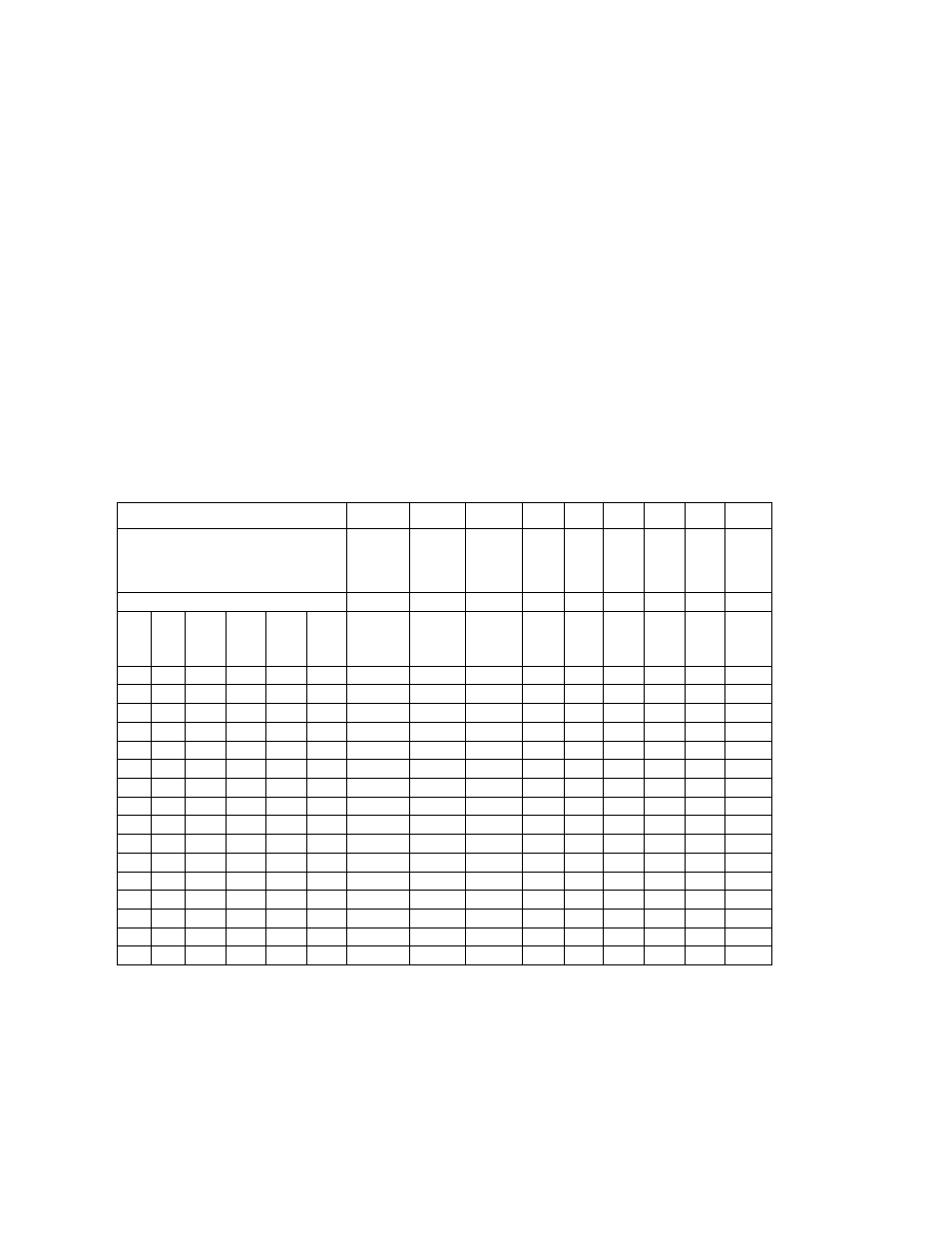
Table 4.1. The ASCII Character Code
COL 0 1
2 3 4 5 6 7
DB6= 0 0
0 0 1 1 1 1
DB5= 0 0
1 1 0 0 1 1
DB4= 0 1
0 1 0 1 0 1
ROW
H
E
X
D
E
C
D
B
3
D
B
2
D
B
1
D
B
0
0 0 0 0 0 0
NUL DLE SP
0 @ P ‘ p
1 1 0 0 0 1
SOH
DC1 ! 1 A Q a q
2 2 0 0 1 0
STX DC2 “ 2 B R b r
3 3 0 0 1 1
ETX DC3 # 3 C S c s
4 4 0 1 0 0
EOT DC4 $ 4
D T d t
5 5 0 1 0 1
ENQ
NAK % 5 E U e u
6 6 0 1 1 0
ACK SYN & 6 F V f v
7 7 0 1 1 1
BEL ETB ‘ 7 G W g w
8 8 1 0 0 0
BS CAN ( 8 H X h x
9 9 1 0 0 1
HT EM ) 9 I Y i y
A
10
1 0 1 0
LF SUB * : J Z j z
B
11
1 0 1 1
VT ESC + ; K [ k {
C
12
1 1 0 0
FF FS , < L \ l l
D
13
1 1 0 1
CR GS - = M ] m }
E
14
1 1 1 0
SO RS . > N ^ n ~
F 15
1 1 1 1
SI US / ? O - o DEL
Non-numeric symbols (e.g., letters) or unprinted characters that are sent in hex data strings are transmitted as
the two characters of their hex address; e.g., “*” is “2A”, Carriage Return is “0D”, Line feed is “0A”, XON=DC1 is
“11”, and XOFF=DC2 is “13”.
4.14 Transmission Voltage Levels
The voltage levels accepted by the meter are those of the standards, and the meter outputs are well regulated
and well within the standards. The two wires carrying the signal are designated “A” and “B”; for RS-232, “B” is
taken as the 0 V ground.
CF 125 INFINITY SC GUIDE
10
M1519/N/0605