7setting decimal point location and roundoff, Decimal point – Cooper Instruments & Systems DFI INFINITY Digital Force Indicator/Controller User Manual
Page 44
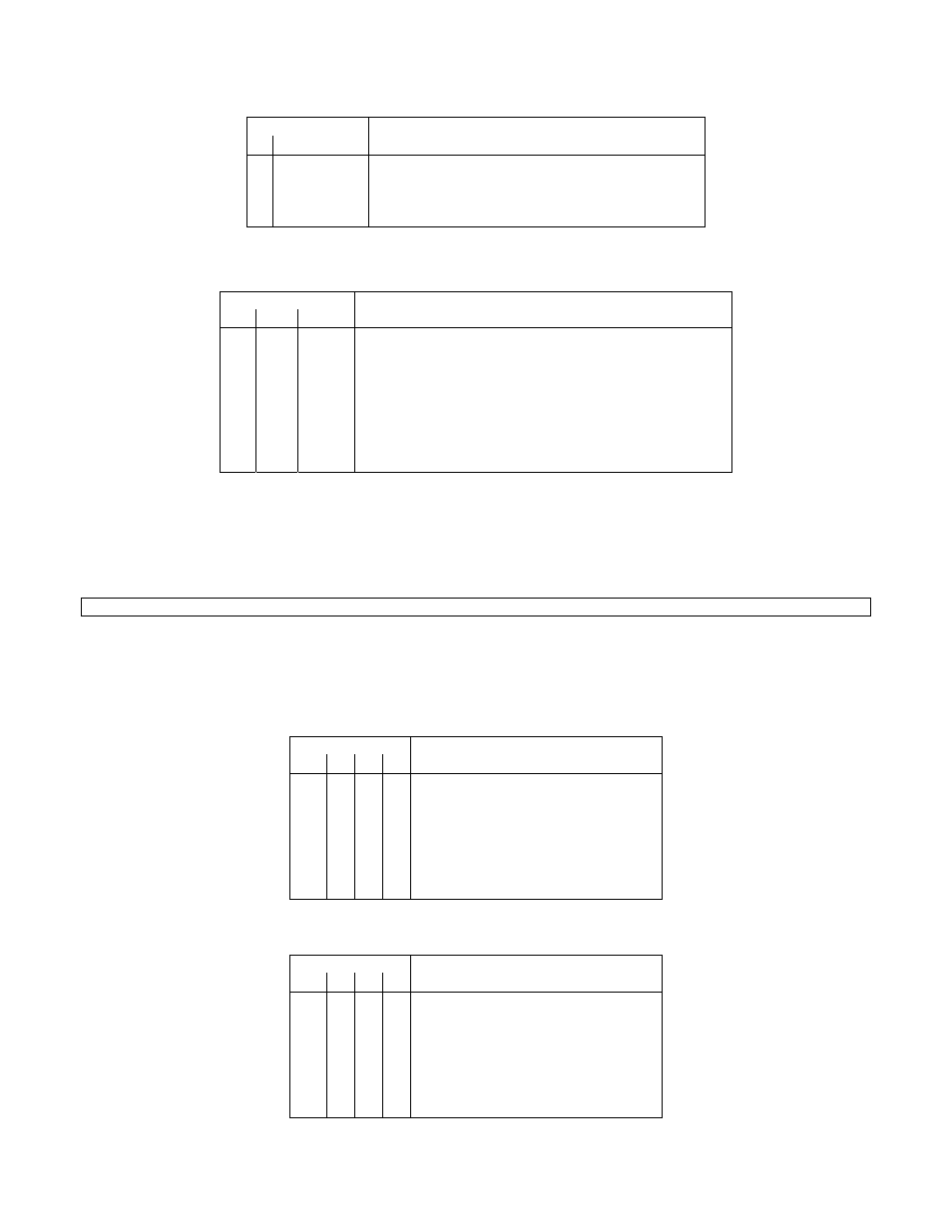
Table 10.12 Input Configuration (“IN CNF”), Bits 4, and 3
BIT NUMBER
4 3
FUNCTION
(VALID IN RTD OR TC MODES)
0 0
No
transmitter
0 1
TC
Transmitter
1 0
RTD
transmitter
1 1
Not
used
Table 10.13. Input Configuration (“IN CNF”), Bits 7,6, and 5
BIT NUMBER
FUNCTION
7 6 5
x
x
0
Using the meter cold Junction if TC mode or 3-wire
linear RTD
x
x
1
Using Remote cold junction if TC mode or 4-wire
linear RTD
x
0
x
Input scale and offset not used
x
1
x
Input scale and offset used
0
x
x
No ratio measurements (only in Bridge or Pot)
1
x
x
Ratio measurements (only in Bridge or Pot) input
EXAMPLE: The computer tells meter HEX #15 to take direct measurements, to use “IN.SC.OF” values (input
scaling and offset to eliminate transmitter span/offset and errors), to use a remote cold junction, to get the input
from a transmitter but to linearize for a thermocouple, to be on a unipolar input scale, to use the SLOW read
rate, and to optimize for 60 Hz (not important in SLOW, however). The byte is now “01101000” or HEX “68”; the
computer sends *15W0A68
NOTE: “If P0A” is transmitted, meter will go to SOFT RESET (RESET1) after completing communication.
10.7 Setting Decimal Point Location and Roundoff (“DEC PT”, “CNT BY”)
This “0C” command suffix encodes these two features in the same byte, MSN for the decimal point and LSN for
the roundoff interval:
Table 10.14. Count By (“CNT BY”), Bits 3, 2, 1, and 0
BIT NUMBER
3 2 1 0
COUNT BY (ROUNDOFF TO)
0 0 0 0 1
0 0 0 1 2
0 0 1 0 5
0 0 1 1 10
0 1 0 0 20
0 1 0 1 50
0 1 1 0 100
Table 10.15. Decimal Point (“DEC PT”), Bits 7,6,5, and 4
BIT NUMBER
7 6 5 4
DECIMAL POINT
0 0 0 0 NONE
0 0 0 1 FFFFFF.
0 0 1 0 FFFFF.F
0 0 1 1 FFFF.FF
0 1 0 0 FFF.FFF
0 1 0 1 FF.FFFF
0 1 1 0 F.FFFFF
CF 125 INFINITY SC GUIDE
40
M1519/N/0605