Aluminum, 400a, H17 plasma / n₂ shield – Tweco Ultra-Cut Torch Data User Manual
Page 70: This art is for reference only
TORCH DATA for Ultra-Cut
8-70
Manual 0-4828
Rev BA
Aluminum
Flow Rates (SLPM / SCFH)
400A
H17
N₂
Preflow
- / -
207 / 439
H17 Plasma / N₂ Shield
Cutflow
47 / 100
173 / 367
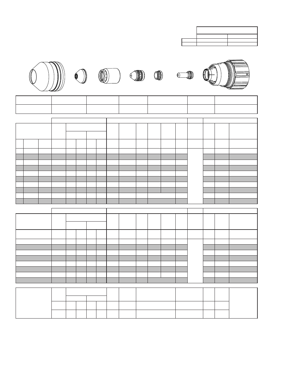
Shield Cup
Shield Cap
Shield Gas
Distributor
Tip
Plasma Gas Distributor
Electrode
Cartridge
21-1305
≤ 1” / 25 mm 21-1304
> 1” / 25 mm 21-1307
21-1303
21-1302
21-1306
21-1301
21-1300
GCM-2010
SC-3000 Torch Height Control (THC)
Basic THC
CNC Control
Material
Thickness
Pre Flow
Pressure
(N₂)
Cut Flow Rates / Pressures
Arc
Voltage Cut Height
THC
Pierce
Delay
Pierce
Ignition
Height
Elevation
Height
Control
Delay
Pierce
Height
without
Elevation
Travel
Speed
CNC
Motion
Delay
Max Kerf Width
@ Rec. Speed
Plasma (H17) Shield (N₂)
ga
(in)
inch
(psi)
Ball (psi) Ball (psi) (Volts) (in) ±0.005 (sec)
(in)
(in)
(sec)
(in)
(ipm)
(sec)
(in)
-
1/2
0.500
30
120 100 NA 100
148
0.200
0.3
0.350 0.250
0.4
N
ot R
ec
omme
nded without
Ele
va
tion He
igh
t
200
0.4
0.195
-
5/8
0.625
30
120 100 NA 100
149
0.200
0.3
0.350 0.250
0.4
180
0.3
0.200
-
3/4
0.750
30
120 100 NA 100
149
0.200
0.6
0.350 0.250
0.4
150
0.4
0.200
-
1
1.000
30
120 100 NA 100
165
0.350
0.7
0.350 0.250
0.4
100
0.5
0.230
-
1 1/4 1.250
30
120 100 NA 100
171
0.350
0.8
0.350 0.300
0.4
80
0.6
0.230
-
1 1/2 1.500
30
120 100 NA 100
167
0.350
1.4
0.350 0.300
0.4
60
1.2
0.240
-
1 3/4 1.750
30
120 100 NA 100
177
0.400
3.0
0.350 0.500
0.4
45
2.0
0.275
-
2
2.000
30
120 100 NA 100
181
0.400
5.5
0.350 0.700
0.4
35
4.5
0.285
-
2 1/4 2.250
30
120 100 NA 100
189
0.400
2.0
Edge Start
0.4
20
2.0
0.310
-
2 1/2 2.500
30
120 100 NA 100
208
0.400
3.0
Edge Start
0.4
10
3.0
0.325
GCM-2010
SC-3000 Torch Height Control (THC)
Basic THC
CNC Control
Material
Thickness
Pre Flow
Pressure
(N₂)
Cut Flow Rates / Pressures
Arc
Voltage Cut Height
THC
Pierce
Delay
Pierce
Ignition
Height
Elevation
Height
Control
Delay
Pierce
Height
without
Elevation
Travel
Speed
CNC
Motion
Delay
Max Kerf Width
@ Rec. Speed
Plasma (H17) Shield (N₂)
(mm)
(Bar)
Ball (Bar) Ball (Bar) (Volts) (mm) ±0.1 (sec)
(mm)
(mm)
(sec)
(mm)
(mm/
min)
(sec)
(mm)
15
2.1
120 6.9
NA
6.9
149
5.1
0.3
8.9
6.4
0.4
N
ot R
ec
omme
nded
without Ele
va
tion Heigh
t
4710
0.3
5.0
20
2.1
120 6.9
NA
6.9
151
5.7
0.6
8.9
6.4
0.4
3620
0.4
5.2
25
2.1
120 6.9
NA
6.9
164
8.7
0.7
8.9
6.4
0.4
2620
0.5
5.8
30
2.1
120 6.9
NA
6.9
169
8.9
0.8
8.9
7.3
0.4
2170
0.6
5.8
35
2.1
120 6.9
NA
6.9
169
8.9
1.1
8.9
7.6
0.4
1770
0.9
6.0
40
2.1
120 6.9
NA
6.9
170
9.3
1.9
8.9
9.1
0.4
1410
1.4
6.4
50
2.1
120 6.9 NA 6.9
180
10.2
5.2
8.9
17.1
0.4
920
4.2
7.2
60
2.1
120 6.9 NA 6.9
198
10.2
2.4
Edge Start
0.4
390
2.4
8.0
Marking
Pre Flow
Pressure
(N₂)
Marking Flow Rates /
Pressures
Arc
Voltage
Marking
Height
Pierce Ignition Height
THC and CNC
Delay
Control
Delay
Travel
Speed
Marking quality
degrades as
thickness
decreases.
50A Arc Current
Plasma (N₂)
Shield (N₂)
Burn-through may
happen for thicknesses
< 1/16” (0.063”) /
1.6 mm.
(psi) /
(Bar)
Ball (psi) /
(Bar)
Ball (psi) /
(Bar) (Volts)
(in) ±0.005 /
(mm) ±0.1
(in) ±0.005 / (mm) ±0.1
(sec)
(sec)
(ipm) /
(mm/ min)
15 / 1.0
80
80 /
5.5
NA
20 /
1.4
92
0.200 / 5.1
0.120 / 3.0
0
0.4
100 /
2540
BOLD TYPE indicates maximum piercing parameters. BOLD ITALIC indicates edge starts only.
Shield Cup
Shield Cap
Shield Gas
Distributor
Tip
Gas
Distributor
Electrode
Cartridge Assembly
This Art Is For Reference Only
Art# A-10444