Aluminum, N₂ plasma / h₂o shield, This art is for reference only – Tweco Ultra-Cut Torch Data User Manual
Page 11
Manual 0-4828
Rev BA 8-11
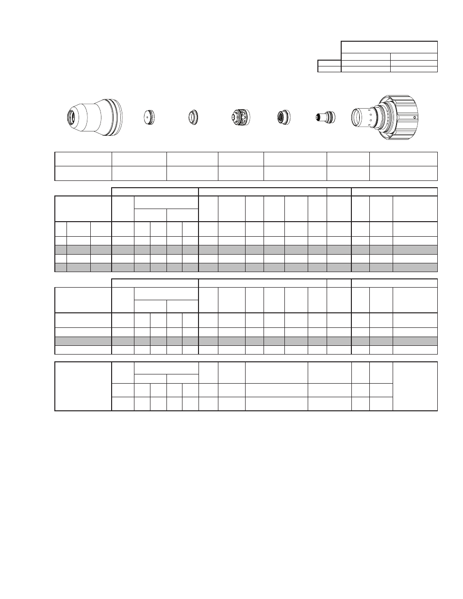
TORCH DATA for Ultra-Cut
Aluminum
Flow Rates
30A
N₂ (SLPM / SCFH)
H₂O (GPH / LPH)
Preflow
9 / 19
4 / 15
N₂ Plasma / H₂O Shield
Cutflow
21 / 44
4 / 15
Shield Cup
Shield Cap
Shield Gas
Distributor
Tip
Plasma Gas Distributor
Electrode
Cartridge
21-1016
21-1033
21-1274
21-1059
21-1045
21-1077
21-1020
GCM-2010
SC-3000 Torch Height Control (THC)
Basic THC
CNC Control
Material
Thickness
Pre Flow
Pressure
(N₂)
Cut Flow Rates / Pressures
Arc
Voltage Cut Height
THC
Pierce
Delay
Pierce
Ignition
Height
Elevation
Height
Control
Delay
Pierce
Height
without
Elevation
Travel
Speed
CNC
Motion
Delay
Max Kerf Width
@ Rec. Speed
Plasma (N₂) Shield (H₂O)
ga
(in)
inch
(psi)
Ball (psi) Ball (psi)* (Volts) (in) ±0.005 (sec)
(in)
(in)
(sec)
(in)
(ipm)
(sec)
(in)
-
-
0.025
96
55
120
4
55
103
0.030
0.0
0.070 0.040
0.4
0.080
230
0.0
0.034
-
-
0.037
96
55
120
4
55
103
0.030
0.1
0.070 0.040
0.4
0.080
220
0.1
0.045
-
-
0.052
96
55
120
4
55
103
0.030
0.2
0.070 0.040
0.4
0.080
150
0.2
0.031
-
-
0.064
96
55
120
4
55
103
0.030
0.2 0.070 0.040
0.4
0.080
110
0.2
0.036
GCM-2010
SC-3000 Torch Height Control (THC)
Basic THC
CNC Control
Material
Thickness
Pre Flow
Pressure
(N₂)
Cut Flow Rates / Pressures
Arc
Voltage Cut Height
THC
Pierce
Delay
Pierce
Ignition
Height
Elevation
Height
Control
Delay
Pierce
Height
without
Elevation
Travel
Speed
CNC
Motion
Delay
Max Kerf Width
@ Rec. Speed
Plasma (N₂) Shield (H₂O)
(mm)
(Bar)
Ball (Bar) Ball (Bar)* (Volts) (mm) ±0.1 (sec) (mm)
(mm)
(sec)
(mm)
(mm/
min)
(sec)
(mm)
1
6.6
55
8.3
4
3.8
103
0.8
0.1
1.8
1.0
0.4
2.0
5310
0.1
1.1
1.5
6.6
55
8.3
4
3.8
103
0.8
0.2
1.8
1.0
0.4
2.0
3210
0.2
0.9
2
6.6
55
8.3
4
3.8
103
0.8
0.2
1.8
1.0
0.4
2.0
1550
0.2
1.1
Marking
Pre Flow
Pressure
(N₂)
Marking Flow Rates /
Pressures
Arc
Voltage
Marking
Height
Pierce Ignition Height
THC and CNC
Delay
Control
Delay
Travel
Speed
Marking quality
degrades as
thickness
decreases.
16A Arc Current
Plasma (N₂)
Shield (N₂)
Burn-through may
happen for thicknesses
< 1/16” (0.063”) /
1.6 mm.
(psi) /
(Bar)
Ball (psi) /
(Bar) Ball
(psi) /
(Bar) (Volts)
(in) ±0.005 /
(mm) ±0.1
(in) ±0.005 / (mm) ±0.1
(sec)
(sec)
(ipm) /
(mm/ min)
20 / 1.4
20
40 /
2.8
70
80 /
5.5
93
0.100 / 2.5
0.100 / 2.5
0
0.6
300 /
7620
BOLD TYPE indicates maximum piercing parameters.
* Pressure of the water supply line should be regulated by customer pressure regulator.
Note 1: Ohmic height sensing is not recommended with water shield. Water on the plate interferes electrically with the ohmic sensing circuit.
Note 2: Water source used for shield must be demineralized.
Electrode
Shield Cap
Tip
Shield Gas
Distributor
Plasma Gas
Distributor
Cartridge
Shield Cup
This Art Is For Reference ONLY
Art # A-07958_AB