Stainless steel, 400a, H35 plasma / n₂ shield – Tweco Ultra-Cut Torch Data User Manual
Page 66
TORCH DATA for Ultra-Cut
8-66
Manual 0-4828
Rev BA
Stainless Steel
Flow Rates (SLPM / SCFH)
400A
H35
N₂
Preflow - / -
207 / 439
H35 Plasma / N₂ Shield
Cut-
flow
47 / 100
173 / 367
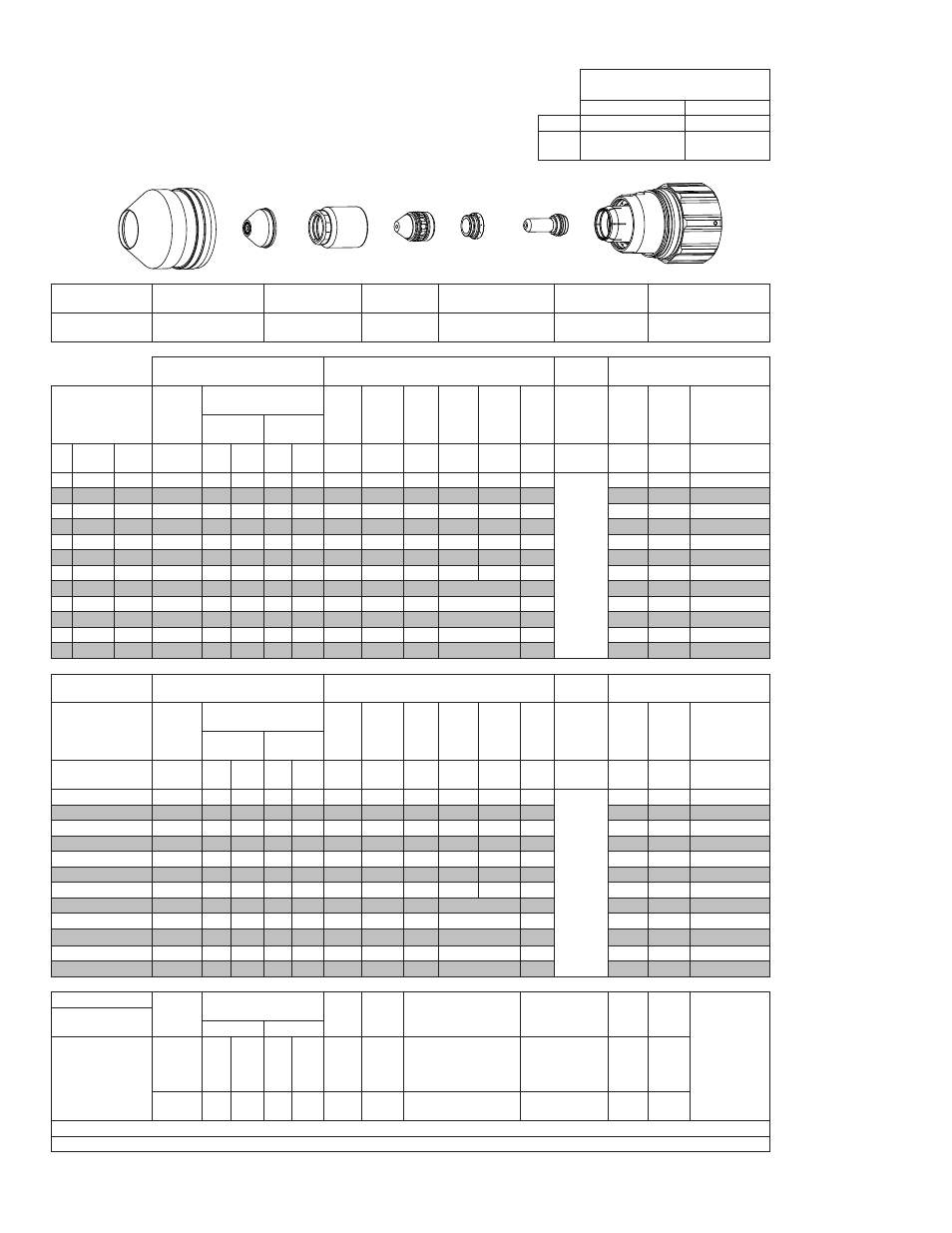
Shield Cup
Shield Cap
Shield Gas Dis-
tributor
Tip
Plasma Gas Distributor Electrode
Cartridge
21-1305
≤ 1” / 25mm 21-1304
> 1” / 25 mm 21-1307
21-1303
21-1302
21-1306
21-1301
21-1300
GCM-2010
SC-3000 Torch Height Control (THC)
Basic
THC
CNC Control
Material
Thickness
Pre Flow
Pressure
(N₂)
Cut Flow Rates / Pres-
sures
Arc
Volt-
age
Cut
Height
THC
Pierce
Delay
Pierce
Igni-
tion
Height
El-
evation
Height
Con-
trol
Delay
Pierce
Height
without
Elevation
Travel
Speed
CNC
Motion
Delay
Max Kerf
Width
@ Rec. Speed
Plasma
(H35)
Shield (N₂)
ga (in)
inch
(psi)
Ball (psi) Ball (psi) (Volts) (in)
±0.005
(sec) (in)
(in)
(sec) (in)
(ipm) (sec)
(in)
-
5/8
0.625
30
120 100 NA 110
155
0.350
0.5
0.400
0.400
0.2
Not
Recom-
mended
without
Elevation
Height
70
0.4
0.230
-
3/4
0.750
30
120 100 NA 110
157
0.350
0.6
0.400
0.400
0.2
60
0.5
0.230
-
1
1.000
30
120 100 NA 110
161
0.350
1.0
0.400
0.500
0.2
45
0.8
0.236
-
1 1/4 1.250
30
120 100 NA 110
163
0.350
1.5
0.400
0.500
0.2
35
1.2
0.235
-
1 1/2 1.500
30
120 100 NA 110
165
0.350
1.8
0.400
0.500
0.2
28
1.3
0.248
-
1 3/4 1.750
30
120 100 NA 110
167
0.350
5.0
0.400
0.750
0.2
20
2.5
0.257
-
2
2.000
30
120 100 NA 110
171
0.350
10.0
0.400
0.750
0.2
17
5.5
0.268
-
2 1/4 2.250
30
120 100 NA 110
175
0.350
3.0
Edge Start
0.2
12
3.0
0.265
-
2 1/2 2.500
30
120 100 NA 110
170
0.350
3.0
Edge Start
0.2
14
3.0
0.260
-
3
3.000
30
120 100 NA 110
177
0.350
3.0
Edge Start
0.2
10
3.0
0.275
-
3 1/2 3.500
30
120 100 NA 110
195
0.350
3.0
Edge Start
0.2
5
3.0
0.280
-
4
4.000
30
120 100 NA 110
210
0.350
4.0
Edge Start
0.2
3.5
4.0
0.290
GCM-2010
SC-3000 Torch Height Control (THC)
Basic
THC
CNC Control
Material
Thickness
Pre Flow
Pressure
(N₂)
Cut Flow Rates / Pres-
sures
Arc
Volt-
age
Cut
Height
THC
Pierce
Delay
Pierce
Igni-
tion
Height
El-
evation
Height
Con-
trol
Delay
Pierce
Height
without
Elevation
Travel
Speed
CNC
Motion
Delay
Max Kerf
Width
@ Rec. Speed
Plasma
(H35)
Shield (N₂)
(mm)
(Bar)
Ball (Bar) Ball (Bar) (Volts) (mm)
±0.1
(sec) (mm) (mm)
(sec) (mm)
(mm/
min)
(sec)
(mm)
15
2.1
120
6.9
NA
7.6
154
8.9
0.5
10.2
10.2
0.2
Not
Recom-
mended
without
Elevation
Height
1850
0.4
5.8
20
2.1
120
6.9
NA
7.6
158
8.9
0.7
10.2
10.5
0.2
1470
0.5
5.9
25
2.1
120
6.9
NA
7.6
161
8.9
1.0
10.2
12.5
0.2
1170
0.8
6.0
30
2.1
120
6.9
NA
7.6
162
8.9
1.4
10.2
12.7
0.2
960
1.1
6.0
35
2.1
120
6.9
NA
7.6
164
8.9
1.7
10.2
12.7
0.2
800
1.3
6.1
40
2.1
120
6.9
NA
7.6
166
8.9
2.8
10.2
14.6
0.2
650
1.7
6.4
50
2.1
120
6.9
NA
7.6
170
8.9
9.4
10.2
19.1
0.2
440
5.1
6.8
60
2.1
120
6.9
NA
7.6
173
8.9
3.0
Edge Start
0.2
330
3.0
6.7
70
2.1
120
6.9
NA
7.6
174
8.9
3.0
Edge Start
0.2
300
3.0
6.8
80
2.1
120
6.9
NA
7.6
182
8.9
3.0
Edge Start
0.2
220
3.0
7.0
90
2.1
120
6.9
NA
7.6
196
8.9
3.1
Edge Start
0.2
120
3.1
7.1
100
2.1
120
6.9
NA
7.6
208
8.9
3.9
Edge Start
0.2
90
3.9
7.3
Marking
Pre Flow
Pressure
(N₂)
Marking Flow Rates /
Pressures
Arc
Volt-
age
Mark-
ing
Height
Pierce Ignition Height
THC and CNC
Delay
Con-
trol
Delay
Travel
Speed
Marking qual-
ity degrades
as thickness
decreases.
50A Arc Current
Plasma (N₂) Shield (N₂)
(psi) /
(Bar)
Ball (psi)
/
(Bar)
Ball (psi)
/
(Bar)
(Volts) (in)
±0.005
/ (mm)
±0.1
(in) ±0.005 / (mm) ±0.1 (sec)
(sec)
(ipm) /
(mm/
min)
15 / 1.0
80
80 /
5.5
NA 20 /
1.4
91
0.250 /
6.4
0.120 / 3.0
0
0.4
100 /
2540
BOLD TYPE indicates maximum piercing parameters. BOLD ITALIC indicates edge starts only.
Note 1: For best results when cutting 4” or 100mm Stainless Steel, H35 can be used for both Plasma and Shield gas.
Shield Cup
Shield Cap
Shield Gas
Distributor
Tip
Gas
Distributor
Electrode
Cartridge Assembly
This Art Is For Reference Only
Art# A-10444