Stainless steel, 200a, H35 plasma / n₂ shield – Tweco Ultra-Cut Torch Data User Manual
Page 39: This art is for reference only
Manual 0-4828
Rev BA 8-39
TORCH DATA for Ultra-Cut
Stainless Steel
Flow Rates (SLPM / SCFH)
200A
H35
N₂
Preflow
- / -
73 / 154
H35 Plasma / N₂ Shield
Cutflow
35 / 74
49 / 103
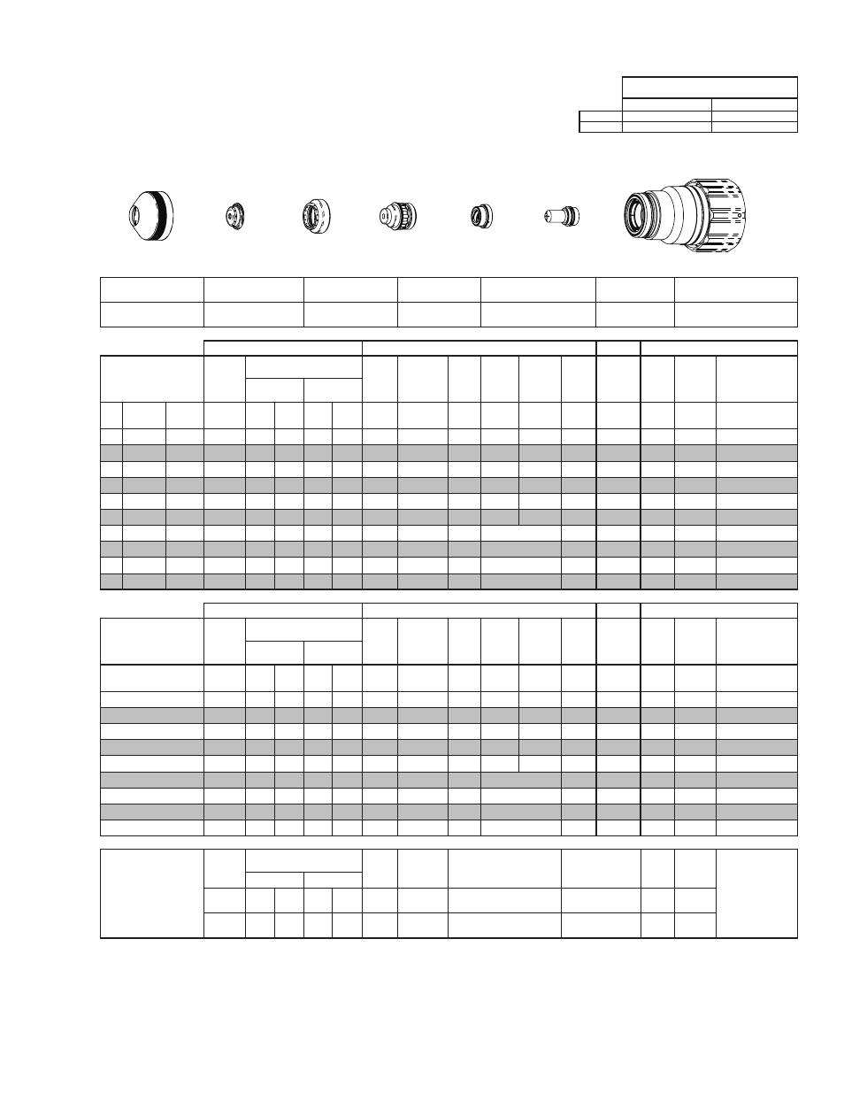
Shield Retainer
Shield Cap
Shield Gas
Distributor
Tip
Plasma Gas Distributor
Electrode
Cartridge
21-1015
21-1073
21-1284
21-1095
21-1042
21-1096
21-1022
GCM-2010
SC-3000 Torch Height Control (THC)
Basic THC
CNC Control
Material
Thickness
Pre Flow
Pressure
(N₂)
Cut Flow Rates / Pressures
Arc
Voltage Cut Height
THC
Pierce
Delay
Pierce
Ignition
Height
Elevation
Height
Control
Delay
Pierce
Height
without
Elevation
Travel
Speed
CNC
Motion
Delay
Max Kerf Width
@ Rec. Speed
Plasma (H35) Shield (N₂)
ga
(in)
inch
(psi)
Ball (psi) Ball (psi) (Volts) (in) ±0.005 (sec)
(in)
(in)
(sec)
(in)
(ipm)
(sec)
(in)
-
3/8
0.375
20
120 100 NA 120
168
0.300
0.5
0.300 0.250
0.4
0.400
90
0.4
0.131
-
1/2
0.500
20
120 100 NA 120
170
0.300
0.8
0.300 0.250
0.3
0.400
65
0.5
0.135
-
5/8
0.625
20
120 100 NA 100
173
0.300
1.0
0.250 0.200
0.2
0.350
50
0.6
0.142
-
3/4
0.750
20
120 100 NA 100
175
0.300
1.4
0.300 0.250
0.2
0.400
40
0.8
0.143
-
7/8
0.875
20
120 100 NA 100
178
0.300
1.8
0.350 0.300
0.2
0.450
35
1.0
0.148
-
1
1.000
20
120 100 NA 120
184
0.350
2.0
0.350 0.300
0.2
0.450
30
1.0
0.162
-
1 1/4 1.250
20
120 100 NA 120
185
0.350
0.5
Edge Start
0.3
Edge
20
0.5
0.170
-
1 1/2 1.500
20
120 100 NA 120
190
0.350
0.5
Edge Start
0.3
Edge
16
0.5
0.175
-
1 3/4 1.750
20
120 100 NA 120
192
0.350
0.5
Edge Start
0.3
Edge
14
0.5
0.179
-
2
2.000
20
120 100 NA 120
193
0.350
0.5
Edge Start
0.3
Edge
12
0.5
0.182
GCM-2010
SC-3000 Torch Height Control (THC)
Basic THC
CNC Control
Material
Thickness
Pre Flow
Pressure
(N₂)
Cut Flow Rates / Pressures
Arc
Voltage Cut Height
THC
Pierce
Delay
Pierce
Ignition
Height
Elevation
Height
Control
Delay
Pierce
Height
without
Elevation
Travel
Speed
CNC
Motion
Delay
Max Kerf Width
@ Rec. Speed
Plasma (H35) Shield (N₂)
(mm)
(Bar)
Ball (Bar) Ball (Bar) (Volts) (mm) ±0.1 (sec)
(mm)
(mm)
(sec)
(mm)
(mm/
min)
(sec)
(mm)
10
1.4
120 6.9
NA
8.3
168
7.6
0.5
7.6
6.4
0.4
10.2
2190
0.4
3.3
12
1.4
120 6.9
NA
8.3
170
7.6
0.7
7.6
6.4
0.3
10.2
1790
0.5
3.4
15
1.4
120 6.9
NA
7.3
172
7.6
0.9
6.7
5.4
0.2
9.2
1380
0.6
3.6
20
1.4
120 6.9
NA
6.9
176
7.6
1.5
8.0
6.7
0.2
10.5
980
0.9
3.7
25
1.4
120 6.9
NA
8.1
183
8.7
2.0
8.9
7.6
0.2
11.4
780
1.0
4.1
30
1.4
120 6.9 NA 8.3
184
8.9
0.5
Edge Start
0.3
Edge
540
0.5
4.3
35
1.4
120 6.9 NA 8.3
188
8.9
0.5
Edge Start
0.3
Edge
460
0.5
4.4
40
1.4
120 6.9 NA 8.3
190
8.9
0.5
Edge Start
0.3
Edge
390
0.5
4.5
50
1.4
120 6.9 NA 8.3
193
8.9
0.5
Edge Start
0.3
Edge
310
0.5
4.6
Marking
Pre Flow
Pressure
(N₂)
Marking Flow Rates /
Pressures
Arc
Voltage
Marking
Height
Pierce Ignition Height
THC and CNC
Delay
Control
Delay
Travel
Speed
Marking quality
degrades as
thickness
decreases.
20A Arc Current
Plasma (N₂)
Shield (N₂)
Burn-through may
happen for thicknesses
< 1/16” (0.063”) /
1.6 mm.
(psi) /
(Bar)
Ball (psi) /
(Bar) Ball
(psi) /
(Bar) (Volts)
(in) ±0.005 /
(mm) ±0.1
(in) ±0.005 / (mm) ±0.1
(sec)
(sec)
(ipm) /
(mm/ min)
15 / 1.0
80
60 /
4.1
NA
80 /
5.5
140 0.120 / 3.0
0.120 / 3.0
0
0.4
300 /
7620
BOLD TYPE indicates maximum piercing parameters. BOLD ITALIC indicates edge starts only.
Cartridge
Electrode
Shield
Shield Gas
Distributor
Tip
Plasma Gas
Distributor
Shield Retainer
Art # A-07917_AC
This Art Is For Reference ONLY