Tweco 7-3480 User Manual
General information, Parts supplied, Installation
July 7, 2003
1
Manual 0-2973
General Information
This kit connects Thermal Dynamics 1Torch Models SL60
or SL100 Torches, or the Thermal Dynamics ATC Adapter,
to Hypertherm* powermax* 600 power supplies with in-
ternal torch connections.
These instructions are important for the proper installa-
tion of the Torches. Read the instructions thoroughly
before attempting the installation. Only a qualified tech-
nician should perform the installation of this kit. Keep
these instructions for reference.
Parts Supplied
The kit includes:
• O2B Adapter Fitting with Wire Harness
• Control Wire Harness
• Barrel Crimp
• Strain Relief
• Instructions
Manual 0-2973
1Torch Adapter
Kit No. 7-3480
Installation Instructions
© 2003 by Thermal Dynamics Corp., Printed in USA. *HYPERTHERM and
powermax are registered trademarks of Hypertherm, Inc.
82 Benning Street, West Lebanon, NH 03784 USA
(603) 298-5711 • www.thermal-dynamics.com
Installation
WARNINGS
Disconnect primary power to the system before
disassembling the torch or torch leads.
DO NOT touch any internal torch parts while the
AC indicator light of the Power Supply is ON.
1. Remove the Power Supply cover per
manufacturer's instructions.
2. Disconnect and remove the original torch from
the Power Supply per manufacturer's instructions.
Remove the brass fitting from the power supply
solenoid connection. Keep the C-clip which se-
cures the brass fitting to the solenoid.
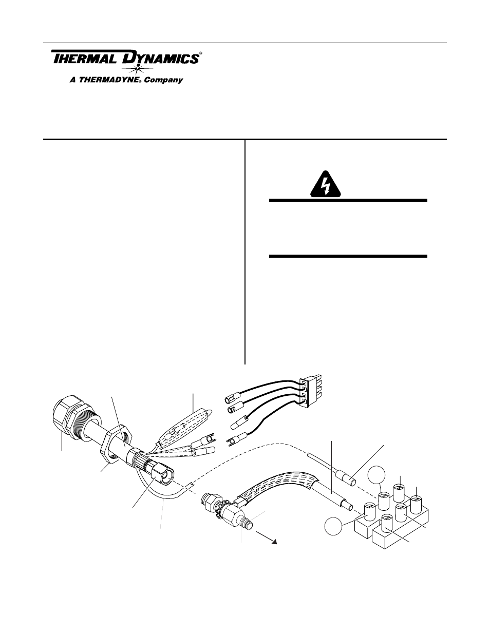
Remove Tie Wrap,
Remove Insulator,
Disconnect Wires
3
5
4
2
6
Power Supply
Terminal Block
A-03606
1
Strain Relief
Torch Leads
Assembly or ATC Adapter
Negative /
Plasma Lead
Pilot Lead Connector-
to Terminal 3
Power Wire
Connector -
to Terminal 5
To Power Supply Main
Circuit Board
Small
Insulating Sleeve
on Pilot Lead
Gas
Fitting
Strain Relief
Securing Nut
To
Power Supply
Torch
Adapter
O-Ring