Mild steel, 300a xtl, O₂ plasma / air shield – Tweco Ultra-Cut Torch Data User Manual
Page 52
TORCH DATA for Ultra-Cut
8-52
Manual 0-4828
Rev BA
Mild Steel
Flow Rates (SLPM / SCFH)
300A XTL
O₂
Air
Preflow
- / -
194 / 412
O₂ Plasma / Air Shield
Cutflow
27 / 58
160 / 340
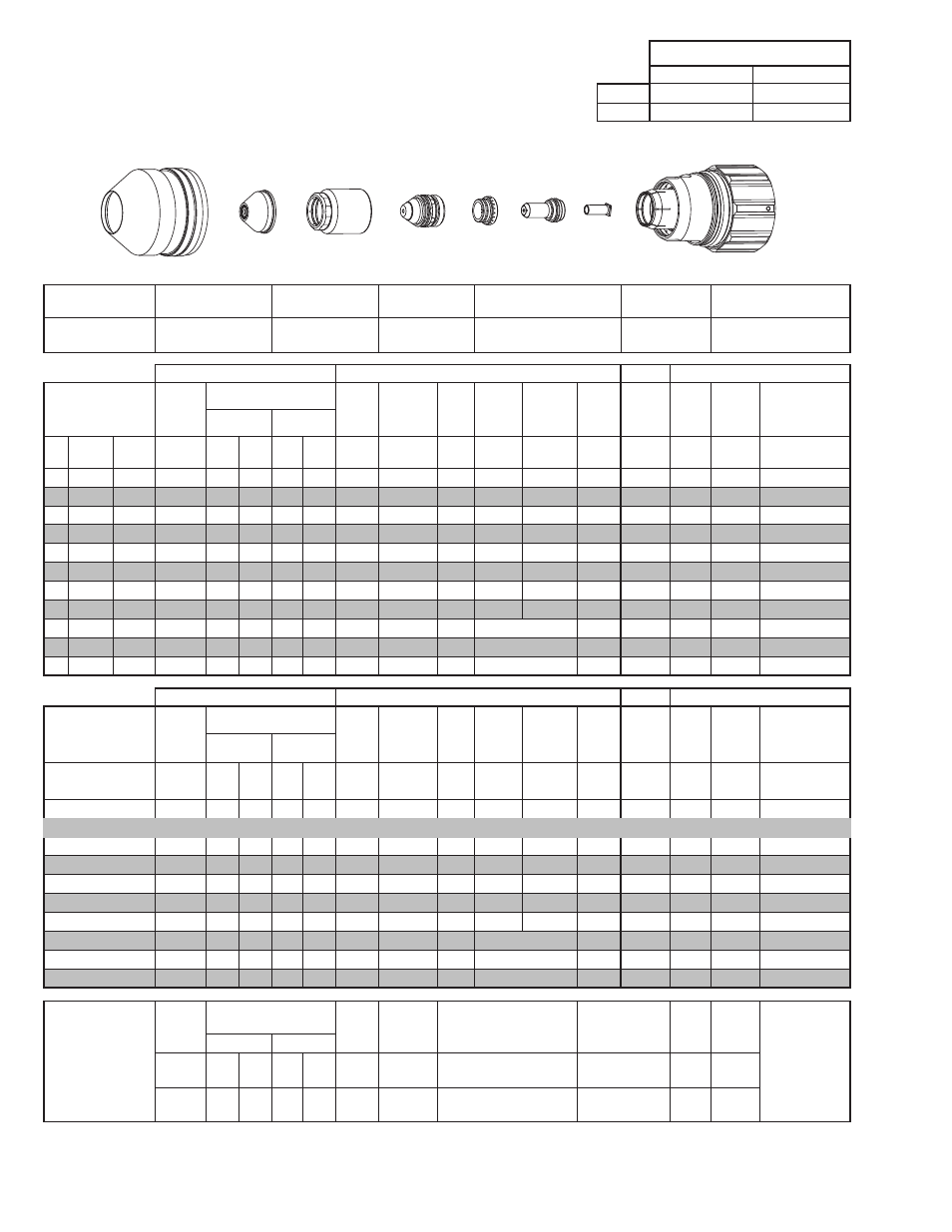
Shield Cup
Shield Cap
Shield Gas Distributor
Tip
Plasma Gas Distributor
Electrode /
Tube
Cartridge
21-1305
21-1105
21-1295
21-1160
21-1042
21-1308
9-7921
21-1300
GCM-2010
SC-3000 Torch Height Control (THC)
Basic THC
CNC Control
Material
Thickness
Pre Flow
Pressure
(Air)
Cut Flow Rates / Pressures
Arc
Voltage Cut Height
THC
Pierce
Delay
Pierce
Ignition
Height
Elevation
Height
Control
Delay
Pierce
Height
without
Elevation
Travel
Speed
CNC
Motion
Delay
Max Kerf Width
@ Rec. Speed
Plasma (O₂)
Shield (Air)
ga
(in)
inch
(psi)
Ball (psi) Ball (psi) (Volts) (in) ±0.005 (sec)
(in)
(in)
(sec)
(in)
(ipm)
(sec)
(in)
-
1/2 0.500
20
100 100 NA 100
159
0.200
0.3
0.400
0.200
0.5
0.450
140
0.2
0.149
-
5/8 0.625
20
100 100 NA 100
161
0.200
0.4
0.400
0.200
0.5
0.450
115
0.3
0.179
-
3/4 0.750
20
100 100 NA 100
158
0.200
0.6
0.400
0.200
0.5
0.450
100
0.4
0.185
-
7/8 0.875
20
100 100 NA 100
161
0.200
0.8
0.400
0.200
0.5
0.450
85
0.6
0.182
-
1
1.000
20
100 100 NA 100
164
0.200
1.1
0.400
0.250
0.5
0.450
70
0.9
0.183
-
1 1/4 1.250
20
100 100 NA 100
164
0.200
1.5
0.400
0.300
0.5
0.500
50
1.2
0.193
-
1 1/2 1.500
20
100 100 NA 100
175
0.200
2.9
0.400
0.350
0.5
0.500
35
2.7
0.208
-
1 3/4 1.750
20
100 100 NA 100
179
0.200
5.3
0.400
0.400
0.5
Edge
25
5.2
0.250
-
2
2.000
20
100 100 NA 100
182
0.200
1.0
Edge Start
0.5
Edge
18
1.0
0.245
-
2 1/2 2.500
20
100 100 NA 100
201
0.200
1.0
Edge Start
0.5
Edge
10
1.0
0.416
-
3
3.000
20
100 100 NA 100
215
0.200
1.0
Edge Start
0.5
Edge
7
1.0
0.500
GCM-2010
SC-3000 Torch Height Control (THC)
Basic THC
CNC Control
Material
Thickness
Pre Flow
Pressure
(Air)
Cut Flow Rates / Pressures
Arc
Voltage Cut Height
THC
Pierce
Delay
Pierce
Ignition
Height
Elevation
Height
Control
Delay
Pierce
Height
without
Elevation
Travel
Speed
CNC
Motion
Delay
Max Kerf Width
@ Rec. Speed
Plasma (O₂)
Shield (Air)
(mm)
(Bar)
Ball (Bar) Ball (Bar) (Volts) (mm) ±0.1 (sec)
(mm)
(mm)
(sec)
(mm)
(mm/
min)
(sec)
(mm)
12
1.4
100 6.9 NA 6.9
159
5.1
0.3
10.2
5.1
0.5
11.4
3700
0.2
3.6
15
1.4
100 6.9 NA 6.9
160
5.1
0.4
10.2
5.1
0.5
11.4
3100
0.3
4.3
20
1.4
100 6.9 NA 6.9
159
5.1
0.7
10.2
5.1
0.5
11.4
2430
0.5
4.7
25
1.4
100 6.9 NA 6.9
164
5.1
1.1
10.2
6.2
0.5
11.4
1830
0.9
4.6
30
1.4
100 6.9 NA 6.9
164
5.1
1.4
10.2
7.3
0.5
12.4
1410
1.1
4.8
35
1.4
100 6.9 NA 6.9
170
5.1
2.2
10.2
8.3
0.5
12.7
1080
2.0
5.1
40
1.4
100 6.9 NA 6.9
176
5.1
3.6
10.2
9.3
0.5
Edge
810
3.4
5.6
50
1.4
100 6.9 NA 6.9
181
5.1
1.0
Edge Start
0.5
Edge
470
1.0
5.9
60
1.4
100 6.9 NA 6.9
196
5.1
1.0
Edge Start
0.5
Edge
310
1.0
9.4
70
1.4
100 6.9 NA 6.9
208
5.1
1.0
Edge Start
0.5
Edge
220
1.0
11.7
Marking
Pre Flow
Pressure
(N₂)
Marking Flow Rates /
Pressures
Arc
Voltage
Marking
Height
Pierce Ignition Height
THC and CNC
Delay
Control
Delay
Travel
Speed
Marking quality
degrades as
thickness
decreases.
30A Arc Current
Plasma (N₂)
Shield (N₂)
(psi) /
(Bar)
Ball (psi) /
(Bar) Ball
(psi) /
(Bar) (Volts)
(in) ±0.005 /
(mm) ±0.1
(in) ±0.005 / (mm) ±0.1
(sec)
(sec)
(ipm) /
(mm/ min)
15 / 1.0
80
60 /
4.1
NA
90 /
6.2
158
0.120 / 3.0
0.120 / 3.0
0
0.5
300 /
7620
BOLD TYPE indicates maximum piercing parameters. BOLD ITALIC indicates edge starts only.
Use CCM 4.5.0 or later and Electronic Cut Chart 2.4.0 or later
This Art Is For Reference Only
Art# A-10270_AB
Shield Cup
Shield Cap
Shield Gas
Distributor
Tip
Gas
Distributor Electrode
Tube
Cartridge Assembly