Aluminum, 200a bevel cut, H35 plasma / n₂ shield – Tweco Ultra-Cut Torch Data User Manual
Page 46: This art is for reference only
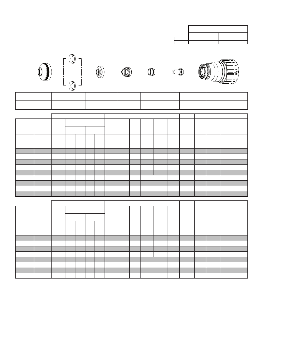
TORCH DATA for Ultra-Cut
8-46
Manual 0-4828
Rev BA
Aluminum
Flow Rates (SLPM / SCFH)
200A Bevel Cut
H35
N₂
Preflow
- / -
62 / 132
H35 Plasma / N₂ Shield
Cutflow
33 / 71
44 / 94
Shield Retainer
Shield Cap
Shield Gas
Distributor
Tip
Plasma Gas Distributor
Electrode
Cartridge
21-1015
< 1” / 25 mm 21-1073
≥ 1” / 25 mm 21-1094
21-1284
21-1095
21-1042
21-1096
21-1022
GCM-2010
SC-3000 Torch Height Control (THC)
Basic THC
CNC Control
Effective
Material
Thickness
Min.
Clearance
Pre Flow
Pressure
(N₂)
Cut Flow Rates / Pressures
Effective Cut
Height
THC
Pierce
Delay
Pierce
Ignition
Height
Elevation
Height
Control
Delay
Pierce
Height
without
Elevation
Travel
Speed
CNC
Motion
Delay
Max Kerf Width
@ Rec. Speed
Plasma (H35) Shield (N₂)
inch
(in)
(psi)
Ball (psi) Ball (psi)
(in)
(sec)
(in)
(in)
(sec)
(in)
(ipm)
(sec)
(in)
0.375
0.080
20
100 100 NA 110 0.300 - 0.550 0.2
0.300 0.250
0.2
0.400
180
0.2
0.113
0.500
0.080
20
100 100 NA 110 0.300 - 0.550 0.2
0.250 0.200
0.4
0.350
150
0.2
0.119
0.625
0.080
20
100 100 NA 110 0.300 - 0.550 0.5
0.250 0.200
0.3
0.350
110
0.3
0.120
0.750
0.080
20
100 100 NA 110 0.300 - 0.550 0.7
0.300 0.250
0.2
0.400
70
0.4
0.130
0.875
0.080
20
100 100 NA 110 0.350 - 0.550 1.0
0.350 0.300
0.2
0.450
55
0.5
0.139
1.000
0.080
20
100 100 NA 110 0.350 - 0.550 1.3
0.400 0.300
0.2
0.500
40
0.7
0.150
1.250
0.080
20
100 100 NA 110 0.400 - 0.550 0.4
Edge Start
0.2
Edge
32
0.4
0.161
1.500
0.080
20
100 100 NA 110 0.400 - 0.550 0.4
Edge Start
0.2
Edge
25
0.4
0.170
1.750
0.080
20
100 100 NA 110 0.400 - 0.550 0.4
Edge Start
0.2
Edge
20
0.4
0.188
2.000
0.080
20
100 100 NA 110 0.400 - 0.550 0.4
Edge Start
0.2
Edge
15
0.4
0.205
GCM-2010
SC-3000 Torch Height Control (THC)
Basic THC
CNC Control
Effective
Material
Thickness
Min.
Clearance
Pre Flow
Pressure
(N₂)
Cut Flow Rates / Pressures
Effective Cut
Height
THC
Pierce
Delay
Pierce
Ignition
Height
Elevation
Height
Control
Delay
Pierce
Height
without
Elevation
Travel
Speed
CNC
Motion
Delay
Max Kerf Width
@ Rec. Speed
Plasma (H35) Shield (N₂)
(mm)
(mm)
(Bar)
Ball (Bar) Ball (Bar)
(mm)
(sec)
(mm)
(mm)
(sec)
(mm)
(mm/
min)
(sec)
(mm)
10
2.0
1.4
100 6.9
NA
7.6
7.6 - 14.0
0.2
7.4
6.2
0.2
10.0
4460
0.2
2.9
12
2.0
1.4
100 6.9
NA
7.6
7.6 - 14.0
0.2
6.6
5.4
0.4
9.2
3980
0.2
3.0
15
2.0
1.4
100 6.9
NA
7.6
7.6 - 14.0
0.4
6.4
5.1
0.3
8.9
3070
0.3
3.0
20
2.0
1.4
100 6.9
NA
7.6
8.0 - 14.0
0.8
8.0
6.7
0.2
10.5
1660
0.4
3.4
25
2.0
1.4
100 6.9
NA 7.6
8.9 - 14.0
1.3
10.0
7.6
0.2
12.5
1060
0.7
3.8
30
2.0
1.4
100 6.9
NA 7.6
10.2 - 14.0
0.4
Edge Start
0.2
Edge
860
0.4
4.0
35
2.0
1.4
100 6.9
NA 7.6
10.2 - 14.0
0.4
Edge Start
0.2
Edge
720
0.4
4.2
40
2.0
1.4
100 6.9
NA 7.6
10.2 - 14.0
0.4
Edge Start
0.2
Edge
600
0.4
4.5
50
2.0
1.4
100 6.9
NA 7.6
10.2 - 14.0
0.4
Edge Start
0.2
Edge
400
0.4
5.2
BOLD TYPE indicates maximum piercing parameters. BOLD ITALIC indicates edge starts only.
Electrode
Shield Retainer
Tip
Art # A-08567_AB
Plasma Gas
Distributor
Cartridge Assembly
This Art Is For Reference ONLY
Shield Cap
Shield Gas
Distributor