Aluminum, Air plasma / air shield, This art is for reference only – Tweco Ultra-Cut Torch Data User Manual
Page 10
TORCH DATA for Ultra-Cut
8-10
Manual 0-4828
Rev BA
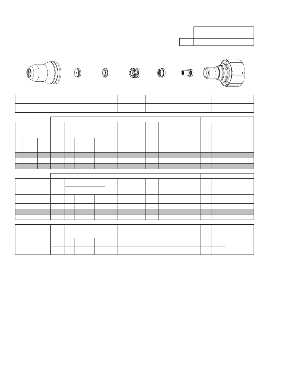
Aluminum
Flow Rates (SLPM / SCFH)
30A
Air
Preflow
19 / 40
Air Plasma / Air Shield
Cutflow
40 / 85
Shield Cup
Shield Cap
Shield Gas
Distributor
Tip
Plasma Gas Distributor
Electrode
Cartridge
21-1016
21-1033
21-1274
21-1059
21-1045
21-1077
21-1020
GCM-2010
SC-3000 Torch Height Control (THC)
Basic THC
CNC Control
Material
Thickness
Pre Flow
Pressure
(Air)
Cut Flow Rates / Pressures
Arc
Voltage Cut Height
THC
Pierce
Delay
Pierce
Ignition
Height
Elevation
Height
Control
Delay
Pierce
Height
without
Elevation
Travel
Speed
CNC
Motion
Delay
Max Kerf Width
@ Rec. Speed
Plasma (Air)
Shield (Air)
ga
(in)
inch
(psi)
Ball (psi) Ball (psi) (Volts) (in) ±0.005 (sec)
(in)
(in)
(sec)
(in)
(ipm)
(sec)
(in)
-
-
0.025
60
60
120 15 120
86
0.020
0.0
0.040 0.030
0.7
0.040
500
0.0
0.029
-
-
0.037
60
60
120 15 120
86
0.020
0.1
0.060 0.040
0.6
0.060
240
0.1
0.046
-
-
0.052
60
60
120 15 120
84
0.020
0.2
0.080 0.040
0.5
0.100
230
0.2
0.034
-
-
0.064
60
60
120 15 120
80
0.020
0.2
0.080 0.040
0.5
0.100
220
0.2
0.036
GCM-2010
SC-3000 Torch Height Control (THC)
Basic THC
CNC Control
Material
Thickness
Pre Flow
Pressure
(Air)
Cut Flow Rates / Pressures
Arc
Voltage Cut Height
THC
Pierce
Delay
Pierce
Ignition
Height
Elevation
Height
Control
Delay
Pierce
Height
without
Elevation
Travel
Speed
CNC
Motion
Delay
Max Kerf Width
@ Rec. Speed
Plasma (Air)
Shield (Air)
(mm)
(Bar)
Ball (Bar) Ball (Bar) (Volts) (mm) ±0.1 (sec)
(mm)
(mm)
(sec)
(mm)
(mm/
min)
(sec)
(mm)
1
4.1
60
8.3
15
8.3
86
0.5
0.1
1.6
1.0
0.6
1.7
6060
0.1
1.1
1.5
4.1
60
8.3
15
8.3
82
0.5
0.2
2.0
1.0
0.5
2.5
5690
0.2
0.9
2
4.1
60
8.3
15
8.3
75
0.5
0.2
2.0
1.0
0.5
2.5
5280
0.2
1.0
Marking
Pre Flow
Pressure
(N₂)
Marking Flow Rates /
Pressures
Arc
Voltage
Marking
Height
Pierce Ignition Height
THC and CNC
Delay
Control
Delay
Travel
Speed
Marking quality
degrades as
thickness
decreases.
16A Arc Current
Plasma (N₂)
Shield (N₂)
Burn-through may
happen for thicknesses
< 1/16” (0.063”) /
1.6 mm.
(psi) /
(Bar)
Ball (psi) /
(Bar) Ball
(psi) /
(Bar) (Volts)
(in) ±0.005 /
(mm) ±0.1
(in) ±0.005 / (mm) ±0.1
(sec)
(sec)
(ipm) /
(mm/ min)
20 / 1.4
20
40 /
2.8
70
80 /
5.5
93
0.100 / 2.5
0.100 / 2.5
0
0.7
300 /
7620
BOLD TYPE indicates maximum piercing parameters.
Electrode
Shield Cap
Tip
Shield Gas
Distributor
Plasma Gas
Distributor
Cartridge
Shield Cup
This Art Is For Reference ONLY
Art # A-07958_AB