Aluminum, 100a, H35 plasma / n₂ shield – Tweco Ultra-Cut Torch Data User Manual
Page 25: This art is for reference only
Manual 0-4828
Rev BA 8-25
TORCH DATA for Ultra-Cut
Aluminum
Flow Rates (SLPM / SCFH)
100A
H35
N₂
Preflow
- / -
62 / 132
H35 Plasma / N₂ Shield
Cutflow
24 / 51
51 / 107
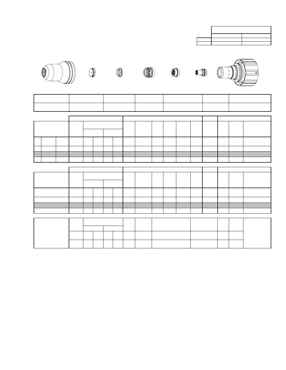
Shield Cup
Shield Cap
Shield Gas
Distributor
Tip
Plasma Gas Distributor
Electrode
Cartridge
21-1016
21-1036
21-1274
21-1062
21-1041
21-1080
21-1020
GCM-2010
SC-3000 Torch Height Control (THC)
Basic THC
CNC Control
Material
Thickness
Pre Flow
Pressure
(N₂)
Cut Flow Rates / Pressures
Arc
Voltage Cut Height
THC
Pierce
Delay
Pierce
Ignition
Height
Elevation
Height
Control
Delay
Pierce
Height
without
Elevation
Travel
Speed
CNC
Motion
Delay
Max Kerf Width
@ Rec. Speed
Plasma (H35) Shield (N₂)
ga
(in)
inch
(psi)
Ball (psi) Ball (psi) (Volts) (in) ±0.005 (sec)
(in)
(in)
(sec)
(in)
(ipm)
(sec)
(in)
-
3/8
0.375
40
67
120 62 120
152
0.154
0.2
0.250 0.200
0.4
0.350
60
0.2
0.105
-
1/2
0.500
40
67
120 62 120
158
0.150
0.2
0.250 0.200
0.4
0.350
50
0.2
0.110
-
5/8
0.625
40
67
120 62 120
160
0.150
0.5
0.250 0.200
0.2
0.350
35
0.5
0.110
GCM-2010
SC-3000 Torch Height Control (THC)
Basic THC
CNC Control
Material
Thickness
Pre Flow
Pressure
(N₂)
Cut Flow Rates / Pressures
Arc
Voltage Cut Height
THC
Pierce
Delay
Pierce
Ignition
Height
Elevation
Height
Control
Delay
Pierce
Height
without
Elevation
Travel
Speed
CNC
Motion
Delay
Max Kerf Width
@ Rec. Speed
Plasma (H35) Shield (N₂)
(mm)
(Bar)
Ball (Bar) Ball (Bar) (Volts) (mm) ±0.1 (sec) (mm)
(mm)
(sec)
(mm)
(mm/
min)
(sec)
(mm)
10
2.8
67
8.3
62
8.3
153
3.9
0.2
6.4
5.1
0.4
8.9
1490
0.2
2.7
12
2.8
67
8.3
62
8.3
157
3.8
0.2
6.4
5.1
0.4
8.9
1330
0.2
2.8
15
2.8
67
8.3
62
8.3
159
3.8
0.4
6.4
5.1
0.3
8.9
990
0.4
2.8
Marking
Pre Flow
Pressure
(N₂)
Marking Flow Rates /
Pressures
Arc
Voltage
Marking
Height
Pierce Ignition Height
THC and CNC
Delay
Control
Delay
Travel
Speed
Marking quality
degrades as
thickness
decreases.
18A Arc Current
Plasma (N₂)
Shield (N₂)
Burn-through may
happen for thicknesses
< 1/16” (0.063”) /
1.6 mm.
(psi) /
(Bar)
Ball (psi) /
(Bar) Ball
(psi) /
(Bar) (Volts)
(in) ±0.005 /
(mm) ±0.1
(in) ±0.005 / (mm) ±0.1
(sec)
(sec)
(ipm) /
(mm/ min)
20 / 1.4
50
40 /
2.8
75
80 /
5.5
125 0.120 / 3.0
0.120 / 3.0
0
0.7
300 /
7620
BOLD TYPE indicates maximum piercing parameters.
Electrode
Shield Cap
Tip
Shield Gas
Distributor
Plasma Gas
Distributor
Cartridge
Shield Cup
This Art Is For Reference ONLY
Art # A-07958_AB