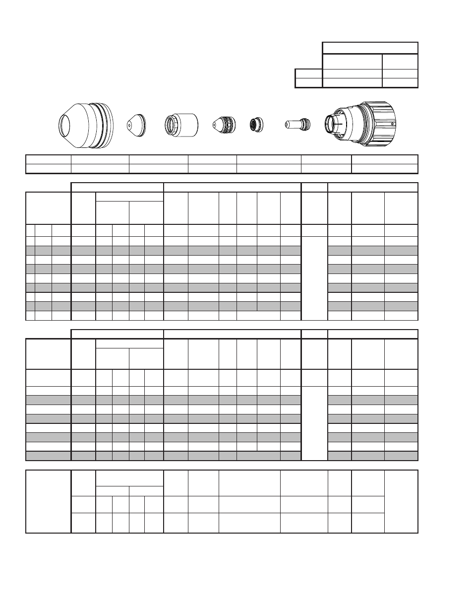
Stainless steel 400a n₂ plasma / h₂o shield, This art is for reference only – Tweco Ultra-Cut Torch Data User Manual
Page 68
TORCH DATA for Ultra-Cut
8-68
Manual 0-4828
Rev BA
Stainless Steel
400A
N₂ Plasma / H₂O Shield
Flow Rates
N₂ (SLPM / SCFH)
H₂O (GPH /
LPH)
Preflow
22 / 47
8 / 30
Cutflow
72 / 153
8 / 30
Shield Cup
Shield Cap
Shield Gas Distributor
Tip
Plasma Gas Distributor
Electrode
Cartridge
21-1305
21-1501
21-1500
21-1302
21-1043
21-1502
21-1300
GCM-2010
SC-3000 Torch Height Control (THC)
Basic THC
CNC Control
Material
Thickness
Pre Flow
Pressure
(N2)
Cut Flow Rates / Pressures
Arc
Voltage Cut Height
THC
Pierce
Delay
Pierce
Ignition
Height
Elevation
Height
Control
Delay
Pierce
Height
without
Elevation
Travel
Speed
CNC Motion
Delay
Max Kerf
Width
@ Rec. Speed
Plasma (N₂) Shield (H₂O)
ga (in)
inch
(psi)
Ball (psi) Ball (psi)* (Volts) (in) ±0.005 (sec)
(in)
(in)
(sec)
(in)
(ipm)
(sec)
(in)
- 3/8 0.375
17
150 119
8
NA
163
0.200
0.4
0.400 0.300
0.2
Not R
ec
ommended without
Ele
va
tion Heigh
t
150
0.3
0.132
- 1/2 0.500
17
150 119
8
NA
164
0.200
0.6
0.450 0.300
0.2
130
0.4
0.200
- 5/8 0.625
17
150 119
8
NA
164
0.200
0.8
0.450 0.400
0.2
110
0.6
0.200
- 3/4 0.750
17
150 119
8
NA
166
0.200
1.2
0.450 0.400
0.2
90
0.7
0.200
-
1
1.000
17
150 119
8
NA
171
0.200
2.0
0.450 0.400
0.2
75
1.0
0.230
- 1 1/4 1.250
17
150 119
8
NA
179
0.250
2.5
0.450 0.450
0.2
40
1.5
0.230
- 1 1/2 1.500
17
150 119
8
NA
184
0.250
3.0
0.450 0.500
0.2
30
2.3
0.240
- 1 3/4 1.750
17
150 119
8
NA
193
0.300
3.5
0.450 0.500
0.2
25
2.7
0.245
-
2
2.000
17
150 119
8
NA
201
0.300
4.0
Edge Start
0.2
17
4.0
0.245
GCM-2010
SC-3000 Torch Height Control (THC)
Basic THC
CNC Control
Material
Thickness
Pre Flow
Pressure
(N2)
Cut Flow Rates / Pressures
Arc
Voltage Cut Height
THC
Pierce
Delay
Pierce
Ignition
Height
Elevation
Height
Control
Delay
Pierce
Height
without
Elevation
Travel
Speed
CNC Motion
Delay
Max Kerf
Width
@ Rec. Speed
Plasma (N₂) Shield (H₂O)
(mm)
(Bar)
Ball (Bar) Ball (Bar)* (Volts) (mm) ±0.1 (sec) (mm)
(mm)
(sec)
(mm)
(mm/
min)
(sec)
(mm)
10
1.2
150
8.2
8
NA
163
5.1
0.4
10.4
7.6
0.2
Not R
ec
ommended without
Ele
va
tion Heigh
t
3730
0.3
3.6
12
1.2
150
8.2
8
NA
164
5.1
0.6
11.2
7.6
0.2
3410
0.4
4.7
15
1.2
150
8.2
8
NA
164
5.1
0.7
11.4
9.5
0.2
2930
0.5
5.1
20
1.2
150
8.2
8
NA
167
5.1
1.3
11.4
10.2
0.2
2230
0.7
5.2
25
1.2
150
8.2
8
NA
171
5.1
1.9
11.4
10.2
0.2
1930
1.0
5.8
30
1.2
150
8.2
8
NA
177
6.0
2.4
11.4
11.1
0.2
1260
1.4
5.8
40
1.2
150
8.2
8
NA
187
6.7
3.1
11.4
12.7
0.2
720
2.4
6.1
50
1.2
150
8.2
8
NA
200
7.6
3.9
Edge Start
0.2
460
3.8
6.2
Marking
45A Arc Current
Burn-through
may happen for
thicknesses <
1/16” (0.063”) /
1.6mm.
Pre Flow
Pressure
(N₂)
Marking Flow Rates /
Pressures
Arc
Voltage
Marking
Height
Pierce Ignition Height THC and CNC Delay Control
Delay
Travel
Speed
Marking
quality
degrades as
thickness
decreases.
Plasma (N₂)
Shield (N₂)
(psi) /
(Bar)
Ball (psi) /
(Bar) Ball
(psi) /
(Bar)
(Volts) (in) ±0.005 /
(mm) ±0.1 (in) ±0.005 / (mm) ±0.1
(sec)
(sec)
(ipm) / (mm/
min)
15 / 1.0 80
60 /
4.1
NA
90 /
6.2
123
0.400 / 10.2
0.400 / 10.2
0
0
200 / 5080
BOLD TYPE indicates maximum piercing parameters. BOLD ITALIC indicates edge starts only.
BOLD TYPE indicates maximum piercing parameters.
* Pressure of the water supply line should be regulated by customer pressure regulator.
Note 1: Ohmic height sensing is not recommended with water shield. Water on the plate interferes electrically with the ohmic sensing circuit.
Note 2: Water source used for shield must be demineralized.
This Art Is For Reference Only
Shield Cup
Shield Cap
Shield Gas
Distributor
Tip
Gas
Distributor
Electrode
Cartridge Assembly
Art# A-10445