Mild steel 400a o₂ plasma / air shield – Tweco Ultra-Cut Torch Data User Manual
Page 65
Manual 0-4828
Rev BA 8-65
TORCH DATA for Ultra-Cut
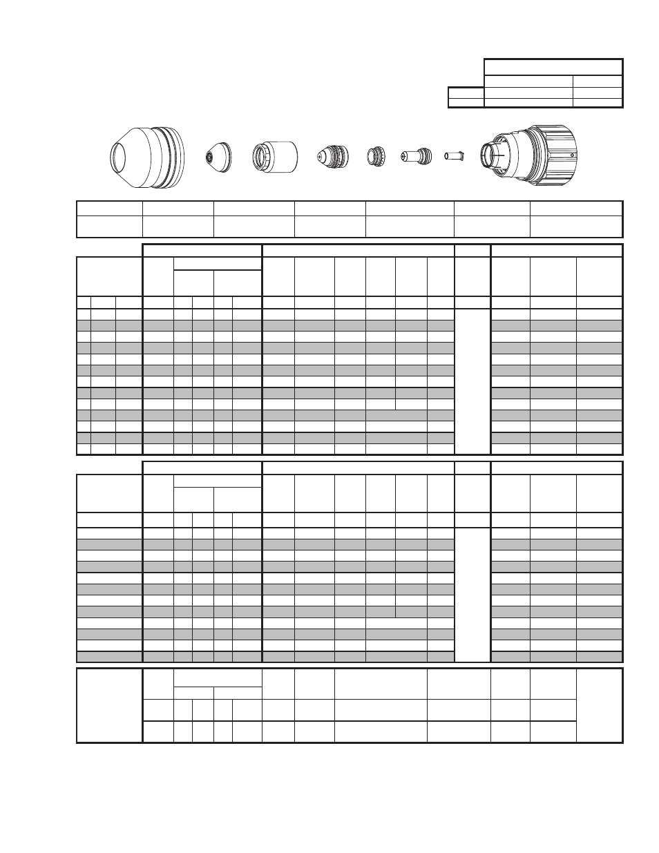
8.07 Standard Cutting 400 Amp
Mild Steel
400A
O₂ Plasma / Air Shield
Flow Rates (SLPM / SCFH)
O₂
Air
Preflow
- / -
232 / 491
Cutflow
33 / 70
203 / 430
Shield Cup
Shield Cap
Shield Gas Distributor
Tip
Plasma Gas Distributor
Electrode
Cartridge
21-1305
21-1304
21-1310
21-1309
21-1042
21-1308
9-7921
21-1300
GCM-2010
SC-3000 Torch Height Control (THC)
Basic THC
CNC Control
Material
Thickness
Pre Flow
Pressure
(Air)
Cut Flow Rates / Pressures
Arc
Voltage Cut Height
THC
Pierce
Delay
Pierce
Ignition
Height
Elevation
Height
Control
Delay
Pierce
Height
without
Elevation
Travel
Speed
CNC Motion
Delay
Max Kerf
Width
@ Rec. Speed
Plasma (O₂) Shield (Air)
ga (in)
inch
(psi)
Ball (psi) Ball
(psi)
(Volts) (in) ±0.005
(sec)
(in)
(in)
(sec)
(in)
(ipm)
(sec)
(in)
- 1/2 0.500
15
80
90
-
80
154
0.200
0.3
0.400
0.200
0.2
Not R
ec
ommended without
Ele
va
tion Heigh
t
150
0.2
0.195
- 5/8 0.625
15
80
90
-
80
154
0.200
0.4
0.400
0.300
0.2
130
0.3
0.200
- 3/4 0.750
15
80
90
-
80
154
0.200
0.6
0.400
0.300
0.2
115
0.8
0.215
- 7/8 0.875
15
80
90
-
80
159
0.200
0.9
0.400
0.500
0.2
100
0.9
0.200
-
1
1.000
15
80
90
-
80
161
0.200
1.1
0.400
0.550
0.2
80
0.9
0.200
- 1 1/4 1.250
15
80
90
-
80
162
0.200
1.5
0.400
0.650
0.2
60
1.3
0.220
- 1 1/2 1.500
15
80
90
-
80
166
0.200
4.0
0.450
0.600
0.2
45
2.5
0.230
- 1 3/4 1.750
15
80
90
-
80
169
0.200
4.5
0.450
0.650
0.2
40
4.0
0.225
-
2
2.000
15
80
90
-
80
170
0.200
7.0
0.450
0.750
0.2
30
6.0
0.225
- 2 1/4 2.250
15
80
90
-
80
170
0.200
3.5
Edge Start
0.2
25
3.5
0.235
- 2 1/2 2.500
15
80
90
-
80
181
0.200
3.0
Edge Start
0.2
15
3.0
0.235
-
3
3.000
15
80
90
-
80
193
0.200
3.0
Edge Start
0.2
10
3.0
0.300
- 3 1/2 3.500
15
80
90
-
80
217
0.200
3.0
Edge Start
0.2
4
3.0
0.360
GCM-2010
SC-3000 Torch Height Control (THC)
Basic THC
CNC Control
Material
Thickness
Pre Flow
Pressure
(Air)
Cut Flow Rates / Pressures
Arc
Voltage Cut Height
THC
Pierce
Delay
Pierce
Ignition
Height
Elevation
Height
Control
Delay
Pierce
Height
without
Elevation
Travel
Speed
CNC Motion
Delay
Max Kerf
Width
@ Rec. Speed
Plasma (O₂) Shield (Air)
(mm)
(Bar)
Ball (Bar) Ball (Bar)
(Volts) (mm) ±0.1
(sec)
(mm)
(mm)
(sec)
(mm)
(mm/ min)
(sec)
(mm)
12
1.0
80 6.2
-
5.5
154
5.1
0.3
10.2
4.5
0.2
Not R
ec
ommended without
Ele
va
tion Heigh
t
3920
0.2
4.9
15
1.0
80 6.2
-
5.5
154
5.1
0.4
10.2
6.9
0.2
3440
0.3
5.0
20
1.0
80 6.2
-
5.5
155
5.1
0.7
10.2
9.1
0.2
2810
0.8
5.3
25
1.0
80 6.2
-
5.5
161
5.1
1.1
10.2
13.8
0.2
2100
0.9
5.1
30
1.0
80 6.2
-
5.5
162
5.1
1.4
10.2
15.8
0.2
1660
1.2
5.4
35
1.0
80 6.2
-
5.5
164
5.1
2.8
10.8
15.9
0.2
1330
1.9
5.7
40
1.0
80 6.2
-
5.5
167
5.1
4.1
11.4
15.6
0.2
1110
2.9
5.8
50
1.0
80 6.2
-
5.5
170
5.1
6.7
11.4
18.7
0.2
790
5.7
5.7
60
1.0
80 6.2
-
5.5
175
5.1
3.3
Edge Start
0.2
520
3.3
6.0
70
1.0
80 6.2
-
5.5
187
5.1
3.0
Edge Start
0.2
320
3.0
6.8
80
1.0
80 6.2
-
5.5
200
5.1
3.0
Edge Start
0.2
210
3.0
8.1
90
1.0
80 6.2
-
5.5
219
5.1
3.0
Edge Start
0.2
90
3.0
9.3
Marking
24A Arc Current
Burn-through
may happen for
thicknesses <
1/16” (0.063”) /
1.6mm.
Pre Flow
Pressure
(N₂)
Marking Flow Rates /
Pressures
Arc
Voltage
Marking
Height
Pierce Ignition Height
THC and CNC Delay Control
Delay
Travel
Speed
Marking
quality
degrades as
thickness
decreases.
Plasma (N₂) Shield (N₂)
(psi) /
(Bar)
Ball (psi) /
(Bar) Ball
(psi) /
(Bar)
(Volts) (in) ±0.005 /
(mm) ±0.1
(in) ±0.005 / (mm) ±0.1
(sec)
(sec)
(ipm) / (mm/
min)
15 / 1.0 50 50 /
3.4 NA 15 / 1.0
110
0.120 / 3.0
0.120 / 3.0
0
0.5
200 / 5080
BOLD TYPE indicates maximum piercing parameters. BOLD ITALIC indicates edge starts only.
BOLD TYPE indicates maximum piercing parameters.
* Pressure of the water supply line should be regulated by customer pressure regulator.
Note 1: Ohmic height sensing is not recommended with water shield. Water on the plate interferes electrically with the ohmic sensing circuit.
Note 2: Water source used for shield must be demineralized.
THC Pierce Delay values shown are the minimum values. It is recommended that this value should be increased depending on the application.
This Art Is For Reference Only
Art# A-10270_AB
Shield Cup
Shield Cap
Shield Gas
Distributor
Tip
Gas
Distributor Electrode
Tube
Cartridge Assembly