Mild steel, 100a, O₂ plasma / air shield – Tweco Ultra-Cut Torch Data User Manual
Page 22: This art is for reference only
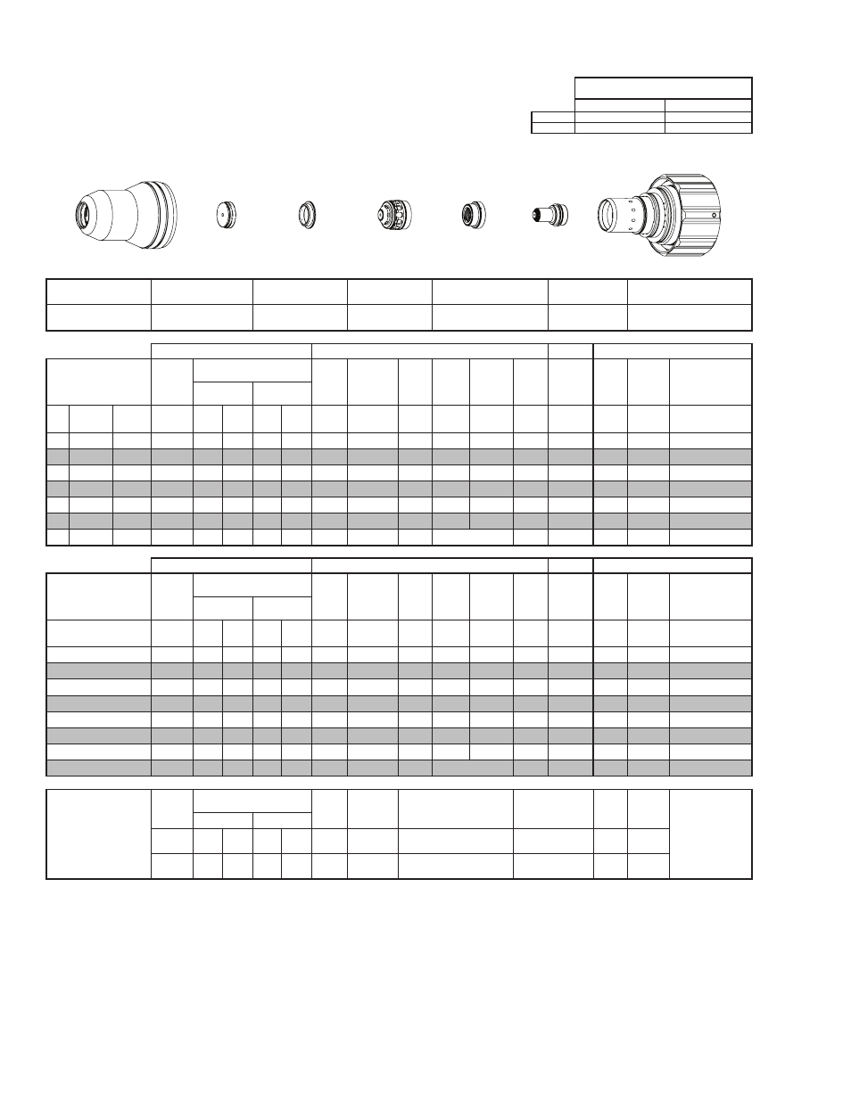
TORCH DATA for Ultra-Cut
8-22
Manual 0-4828
Rev BA
Mild Steel
Flow Rates (SLPM / SCFH)
100A
O₂
Air
Preflow
- / -
38 / 81
O₂ Plasma / Air Shield
Cutflow
16 / 35
27 / 58
Shield Cup
Shield Cap
Shield Gas
Distributor
Tip
Plasma Gas Distributor
Electrode
Cartridge
21-1016
21-1027
21-1272
21-1153
21-1041
21-1171
21-1020
GCM-2010
SC-3000 Torch Height Control (THC)
Basic THC
CNC Control
Material
Thickness
Pre Flow
Pressure
(Air)
Cut Flow Rates / Pressures
Arc
Voltage Cut Height
THC
Pierce
Delay
Pierce
Ignition
Height
Elevation
Height
Control
Delay
Pierce
Height
without
Elevation
Travel
Speed
CNC
Motion
Delay
Max Kerf Width
@ Rec. Speed
Plasma (O₂)
Shield (Air)
ga
(in)
inch
(psi)
Ball (psi) Ball (psi) (Volts) (in) ±0.005 (sec)
(in)
(in)
(sec)
(in)
(ipm)
(sec)
(in)
10
-
0.135
40
55
120 80 120
138
0.070
0.2
0.125 0.120
0.6
0.200
280
0.2
0.065
-
3/16
0.188
40
55
120 80 120
140
0.090
0.2
0.125 0.120
0.6
0.200
190
0.2
0.070
-
1/4
0.250
40
55
120 80 120
141
0.090
0.3
0.125 0.120
0.5
0.200
145
0.3
0.078
-
3/8
0.375
40
55
120 80 120
143
0.110
0.4
0.150 0.150
0.4
0.250
90
0.4
0.085
-
1/2
0.500
40
55
120 80 120
147
0.120
0.6
0.200 0.150
0.4
0.300
60
0.6
0.097
-
5/8
0.625
40
55
120 80 120
148
0.120
0.8
0.250 0.200
0.4
0.350
50
0.8
0.100
-
3/4
0.750
40
55
120 80 120
157
0.150
3.5
Edge Start
0.4
Edge
25
2.0
0.125
GCM-2010
SC-3000 Torch Height Control (THC)
Basic THC
CNC Control
Material
Thickness
Pre Flow
Pressure
(Air)
Cut Flow Rates / Pressures
Arc
Voltage Cut Height
THC
Pierce
Delay
Pierce
Ignition
Height
Elevation
Height
Control
Delay
Pierce
Height
without
Elevation
Travel
Speed
CNC
Motion
Delay
Max Kerf Width
@ Rec. Speed
Plasma (O₂)
Shield (Air)
(mm)
(Bar)
Ball (Bar) Ball (Bar) (Volts) (mm) ±0.1 (sec)
(mm)
(mm)
(sec)
(mm)
(mm/
min)
(sec)
(mm)
4
2.8
55
8.3
80
8.3
139
2.0
0.2
3.2
3.0
0.6
5.1
6140
0.2
1.7
5
2.8
55
8.3
80
8.3
140
2.3
0.2
3.2
3.0
0.6
5.1
4660
0.2
1.8
6
2.8
55
8.3
80
8.3
141
2.3
0.3
3.2
3.0
0.5
5.1
3940
0.3
1.9
8
2.8
55
8.3
80
8.3
142
2.6
0.4
3.5
3.4
0.4
5.7
2960
0.4
2.1
10
2.8
55
8.3
80
8.3
144
2.8
0.4
4.0
3.8
0.4
6.5
2170
0.4
2.2
12
2.8
55
8.3
80
8.3
146
3.0
0.6
4.8
3.8
0.4
7.3
1690
0.6
2.4
15
2.8
55
8.3
80
8.3
148
3.0
0.7
6.0
4.7
0.4
8.5
1340
0.7
2.5
20
2.8
55
8.3
80
8.3
157
3.8
4.3
Edge Start
0.4
Edge
640
2.4
3.2
Marking
Pre Flow
Pressure
(N₂)
Marking Flow Rates /
Pressures
Arc
Voltage
Marking
Height
Pierce Ignition Height
THC and CNC
Delay
Control
Delay
Travel
Speed
Marking quality
degrades as
thickness
decreases.
17A Arc Current
Plasma (N₂)
Shield (N₂)
Burn-through may
happen for thicknesses
< 1/16” (0.063”) /
1.6 mm.
(psi) /
(Bar)
Ball (psi) /
(Bar)
Ball (psi) /
(Bar) (Volts)
(in) ±0.005 /
(mm) ±0.1
(in) ±0.005 / (mm) ±0.1
(sec)
(sec)
(ipm) /
(mm/ min)
20 / 1.4
50
40 /
2.8
100
80 /
5.5
144 0.120 / 3.0
0.120 / 3.0
0
0.4
300 /
7620
BOLD TYPE indicates maximum piercing parameters. BOLD ITALIC indicates edge starts only.
Electrode
Shield Cap
Tip
Shield Gas
Distributor
Plasma Gas
Distributor
Cartridge
Shield Cup
This Art Is For Reference ONLY
Art # A-07958_AB