Stainless steel, 200a bevel cut, N₂ plasma / h₂o shield – Tweco Ultra-Cut Torch Data User Manual
Page 45: This art is for reference only
Manual 0-4828
Rev BA 8-45
TORCH DATA for Ultra-Cut
Stainless Steel
Flow Rates
200A Bevel Cut
N₂ (SLPM / SCFH)
H₂O (GPH / LPH)
Preflow
13 / 28
5 / 19
N₂ Plasma / H₂O Shield
Cutflow
25 / 53
5 / 19
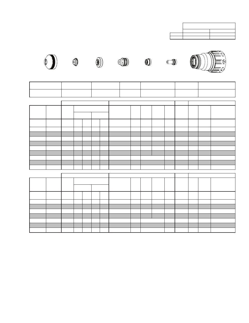
Shield Retainer
Shield Cap
Shield Gas
Distributor
Tip
Plasma Gas Distributor
Electrode
Cartridge
21-1015
21-1049
21-1284
21-1067
21-1043
21-1089
21-1022
GCM-2010
SC-3000 Torch Height Control (THC)
Basic THC
CNC Control
Effective
Material
Thickness
Min.
Clearance
Pre Flow
Pressure
(N₂)
Cut Flow Rates / Pressures
Effective Cut
Height
THC
Pierce
Delay
Pierce
Ignition
Height
Elevation
Height
Control
Delay
Pierce
Height
without
Elevation
Travel
Speed
CNC
Motion
Delay
Max Kerf Width
@ Rec. Speed
Plasma (N₂) Shield (H₂O)
inch
(in)
(psi)
Ball (psi) Ball (psi)*
(in)
(sec)
(in)
(in)
(sec)
(in)
(ipm)
(sec)
(in)
0.375
0.080
20
80
90
5
55
0.160 - 0.550 0.1
0.200 0.150
0.4
0.300
95
0.1
0.110
0.500
0.080
20
80
90
5
55
0.160 - 0.550 0.4
0.200 0.150
0.2
0.300
85
0.4
0.115
0.625
0.080
20
80
90
5
55
0.180 - 0.550 0.8
0.200 0.150
0.2
0.300
65
0.5
0.122
0.750
0.080
20
80
90
5
55
0.200 - 0.550 1.2
0.200 0.150
0.2
0.300
50
0.7
0.133
0.875
0.080
20
80
90
5
55
0.250 - 0.550 1.7
0.300 0.250
0.2
0.400
40
0.9
0.149
1.000
0.080
20
80
90
5
55 0.300 - 0.550 1.9
0.350 0.300
0.2
0.450
35
1.0
0.148
1.250
0.080
20
80
90
5
55 0.300 - 0.550 0.4
Edge Start
0.2
Edge
20
0.4
0.176
1.500
0.080
20
80
90
5
55 0.350 - 0.450 0.4
Edge Start
0.2
Edge
10
0.4
0.211
1.750
0.080
20
80
90
5
55 0.350 - 0.450 0.4
Edge Start
0.2
Edge
8
0.4
0.216
GCM-2010
SC-3000 Torch Height Control (THC)
Basic THC
CNC Control
Effective
Material
Thickness
Min.
Clearance
Pre Flow
Pressure
(N₂)
Cut Flow Rates / Pressures
Effective Cut
Height
THC
Pierce
Delay
Pierce
Ignition
Height
Elevation
Height
Control
Delay
Pierce
Height
without
Elevation
Travel
Speed
CNC
Motion
Delay
Max Kerf Width
@ Rec. Speed
Plasma (N₂) Shield (H₂O)
(mm)
(mm)
(Bar)
Ball (Bar) Ball (Bar)*
(mm)
(sec)
(mm)
(mm)
(sec)
(mm)
(mm/
min)
(sec)
(mm)
10
2.0
1.4
80
6.2
5
3.8
4.1 - 14.0
0.1
5.1
3.8
0.4
7.6
2380
0.1
2.8
15
2.0
1.4
80
6.2
5
3.8
4.4 - 14.0
0.7
5.1
3.8
0.2
7.6
1790
0.5
3.0
20
2.0
1.4
80
6.2
5
3.8
5.5 - 14.0
1.3
5.8
4.6
0.2
8.4
1190
0.8
3.5
25
2.0
1.4
80
6.2
5
3.8
7.5 - 14.0
1.9
8.7
7.5
0.2
11.3
910
1.0
3.8
30
2.0
1.4
80
6.2
5
3.8
7.3 - 14.0
0.4
Edge Start
0.2
Edge
580
0.4
4.2
35
2.0
1.4
80
6.2
5
3.8
8.3 - 11.4
0.4
Edge Start
0.2
Edge
380
0.4
4.9
40
2.0
1.4
80
6.2
5
3.8
8.9 - 11.4
0.4
Edge Start
0.2
Edge
240
0.4
5.4
BOLD TYPE indicates maximum piercing parameters. BOLD ITALIC indicates edge starts only.
* Pressure of the water supply line should be regulated by customer pressure regulator.
Note 1: Ohmic height sensing is not recommended with water shield. Water on the plate interferes electrically with the ohmic sensing circuit.
Note 2: Water source used for shield must be demineralized.
Cartridge
Electrode
Shield
Shield Gas
Distributor
Tip
Plasma Gas
Distributor
Shield Retainer
Art # A-08552
This Art Is For Reference ONLY