Stainless steel, 200a, N₂ plasma / h₂o shield – Tweco Ultra-Cut Torch Data User Manual
Page 40: This art is for reference only
TORCH DATA for Ultra-Cut
8-40
Manual 0-4828
Rev BA
Stainless Steel
Flow Rates
200A
N₂ (SLPM / SCFH)
H₂O (GPH / LPH)
Preflow
13 / 28
5 / 19
N₂ Plasma / H₂O Shield
Cutflow
25 / 53
5 / 19
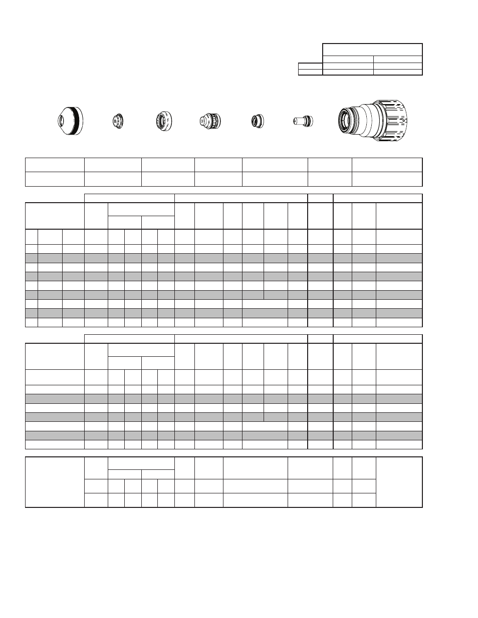
Shield Retainer
Shield Cap
Shield Gas
Distributor
Tip
Plasma Gas Distributor
Electrode
Cartridge
21-1015
21-1049
21-1284
21-1067
21-1043
21-1089
21-1022
GCM-2010
SC-3000 Torch Height Control (THC)
Basic THC
CNC Control
Material
Thickness
Pre Flow
Pressure
(N₂)
Cut Flow Rates / Pressures
Arc
Voltage Cut Height
THC
Pierce
Delay
Pierce
Ignition
Height
Elevation
Height
Control
Delay
Pierce
Height
without
Elevation
Travel
Speed
CNC
Motion
Delay
Max Kerf Width
@ Rec. Speed
Plasma (N₂) Shield (H₂O)
ga
(in)
inch
(psi)
Ball (psi) Ball (psi)* (Volts) (in) ±0.005 (sec)
(in)
(in)
(sec)
(in)
(ipm)
(sec)
(in)
-
3/8
0.375
20
80
90
5
55
155
0.160
0.1
0.200 0.150
0.4
0.300
95
0.1
0.110
-
1/2
0.500
20
80
90
5
55
156
0.160
0.4
0.200 0.150
0.2
0.300
85
0.4
0.115
-
5/8
0.625
20
80
90
5
55
158
0.180
0.8
0.200 0.150
0.2
0.300
65
0.5
0.122
-
3/4
0.750
20
80
90
5
55
163
0.200
1.2
0.200 0.150
0.2
0.300
50
0.7
0.133
-
7/8
0.875
20
80
90
5
55
177
0.250
1.7
0.300 0.250
0.2
0.400
40
0.9
0.149
-
1
1.000
20
80
90
5
55
183
0.300
1.9
0.350 0.300
0.2
0.450
35
1.0
0.148
-
1 1/4 1.250
20
80
90
5
55
185
0.300
0.4
Edge Start
0.2
Edge
20
0.4
0.176
-
1 1/2 1.500
20
80
90
5
55
200
0.350
0.4
Edge Start
0.2
Edge
10
0.4
0.211
-
1 3/4 1.750
20
80
90
5
55
207
0.350
0.4
Edge Start
0.2
Edge
8
0.4
0.216
GCM-2010
SC-3000 Torch Height Control (THC)
Basic THC
CNC Control
Material
Thickness
Pre Flow
Pressure
(N₂)
Cut Flow Rates / Pressures
Arc
Voltage Cut Height
THC
Pierce
Delay
Pierce
Ignition
Height
Elevation
Height
Control
Delay
Pierce
Height
without
Elevation
Travel
Speed
CNC
Motion
Delay
Max Kerf Width
@ Rec. Speed
Plasma (N₂) Shield (H₂O)
(mm)
(Bar)
Ball (Bar) Ball (Bar)* (Volts) (mm) ±0.1 (sec) (mm)
(mm)
(sec)
(mm)
(mm/
min)
(sec)
(mm)
10
1.4
80
6.2
5
3.8
155
4.1
0.1
5.1
3.8
0.4
7.6
2380
0.1
2.8
15
1.4
80
6.2
5
3.8
157
4.4
0.7
5.1
3.8
0.2
7.6
1790
0.5
3.0
20
1.4
80
6.2
5
3.8
167
5.5
1.3
5.8
4.6
0.2
8.4
1190
0.8
3.5
25
1.4
80
6.2
5
3.8
182
7.5
1.9
8.7
7.5
0.2
11.3
910
1.0
3.8
30
1.4
80
6.2
5
3.8
181
7.3
0.4
Edge Start
0.2
Edge
580
0.4
4.2
35
1.4
80
6.2
5
3.8
193
8.3
0.4
Edge Start
0.2
Edge
380
0.4
4.9
40
1.4
80
6.2
5
3.8
202
8.9
0.4
Edge Start
0.2
Edge
240
0.4
5.4
Marking
Pre Flow
Pressure
(N₂)
Marking Flow Rates /
Pressures
Arc
Voltage
Marking
Height
Pierce Ignition Height
THC and CNC
Delay
Control
Delay
Travel
Speed
Marking quality
degrades as
thickness
decreases.
20A Arc Current
Plasma (N₂)
Shield (N₂)
Burn-through may
happen for thicknesses
< 1/16” (0.063”) /
1.6 mm.
(psi) /
(Bar)
Ball (psi) /
(Bar) Ball
(psi) /
(Bar) (Volts)
(in) ±0.005 /
(mm) ±0.1
(in) ±0.005 / (mm) ±0.1
(sec)
(sec)
(ipm) /
(mm/ min)
15 / 1.0
80
60 /
4.1
NA
80 /
5.5
140 0.120 / 3.0
0.120 / 3.0
0
0.4
300 /
7620
BOLD TYPE indicates maximum piercing parameters. BOLD ITALIC indicates edge starts only.
* Pressure of the water supply line should be regulated by customer pressure regulator.
Note 1: Ohmic height sensing is not recommended with water shield. Water on the plate interferes electrically with the ohmic sensing circuit.
Note 2: Water source used for shield must be demineralized.
Cartridge
Electrode
Shield
Shield Gas
Distributor
Tip
Plasma Gas
Distributor
Shield Retainer
Art # A-07917_AC
This Art Is For Reference ONLY