2 gas flow, Gas flow diagram, Display – Metrohm 774 Oven Sample Processor User Manual
Page 45
4.2 Gas flow
774 Oven Sample Processor, Instructions for use
39
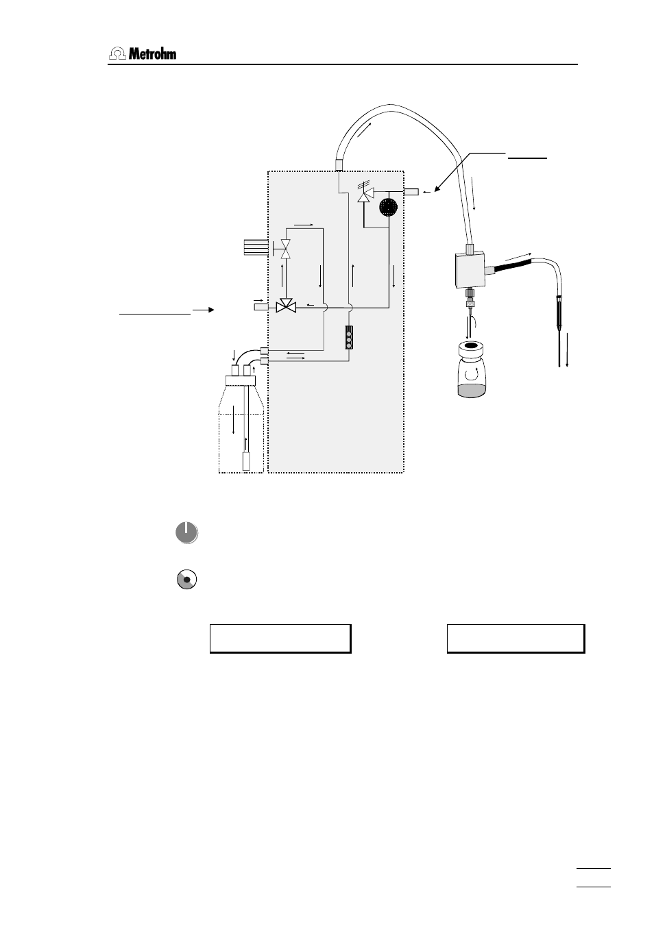
Gas flow diagram:
inlet filter
flow meter
pump
pressure control
valve
gas flow
control knob
solenoid
valve
Air/N2 in
from Drying flask
to Drying flask
tower
outlet needle
injection
needle
sample
titration cell
conveying tubing
left-hand
instrument
side
Gas flow
Air/N
2
in
The gas flow can be set manually with the help of the gas flow regulator and
the flowmeter. The flow rate of the carrier gas is shown on the display in
mL/min or L/h so that it is easy to set the required gas flow with the rotary
knob of the gas flow regulator. A gas flow of 20 to 100 mL/min is required;
this depends on the determination method and moisture in the sample.
Display:
******** counter 1/36
110°C 55 mL/min ready
or:
(
press
gas flow 55 mL/min
heater temp. 120°C
The gas flow is monitored automatically. A lower and an upper limit can be
defined for the gas flow; if these are undercut or exceeded an error mes-
sage is displayed. It is recommended that the safety limits (min. flow and
max. flow) are not set too closely for gas flow monitoring. A range of ap-
prox. 30 mL/min should be set.
During needle penetration and removal the gas flow should be switched off
as large variations in gas pressure occur during these processes. This
avoids unnecessary error messages.
air inlet
inert gas inlet