Figure 2 baud rate rotary switch layout, Led operation, Figure 3 led labeling – Bird Technologies BDS-Manual User Manual
Page 66: Table 5-1 network status led operation (net)
52
Rotary switches S2 (MSD) and S3 (LSD) are used to select the DeviceNet MAC ID (Node Address). The valid range of
addresses is: 0-63. Switch combinations that produce an address greater than 63 will force the device into a “MAC ID
software configuration mode”. While in the “MAC ID software configuration mode” the device MAC ID will be set to
the last MAC ID that the device was powered up at and will allow software configuration tools to modify the value of
the MAC ID.
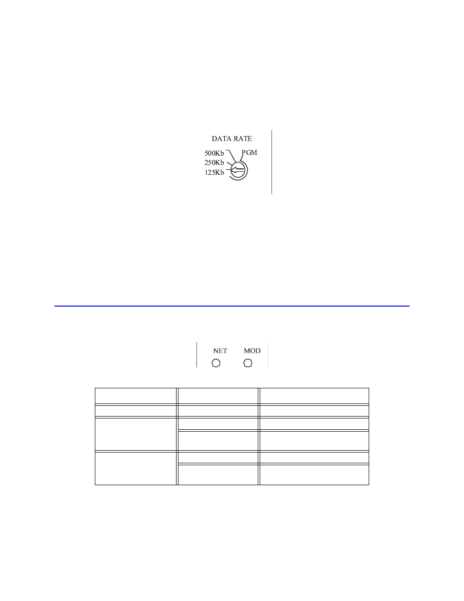
Figure 2 Baud Rate Rotary Switch Layout
The S1 rotary switch (DATA RATE) is used to select the DeviceNet baud rate. The following is a valid range of baud
rates:
•
0 – 125kbps
•
1 – 250kbps
•
2 – 500kbps
•
3 and above – “Baud Rate software configuration mode”
All values above 2 will force the device into a “Baud Rate configuration mode”. While in the “Baud Rate configura-
tion mode” the device baud rate will be set to the last baud rate the device was powered up at and will allow soft-
ware configuration tools to modify the value of the baud rate.
LED Operation
Two LED’s are provided on the front panel of the BDS: Network Status and Module Status. See the figure below.
Figure 3 LED Labeling
Table 5-1 Network Status LED Operation (NET)
LED Color
LED State
Description
None
Off
No power applied to device.
Red
Solid
Unrecoverable fault detected.
Flashing
Output error or configuration error
(recoverable fault).
Green
Solid
Normal runtime operation.
Flashing
Device is idle or not allocated to a
master.