Connecting the sensor and receiver cables, Figure 4 receiver cable connections from sensor – Bird Technologies BDS-Manual User Manual
Page 21
7
Connecting the Sensor and Receiver Cables
1.
Connect the current and voltage cables to the sensor (Figure ).
2.
Torque the SMA connectors to 1.55 Nm (±0.15 Nm).
Note: The SMA connector on the current sensor cable has a standard center
conductor and the SMA connector on the voltage sensor cable has a reverse
polarity center conductor.
3.
Connect the temperature/data cable to the sensor.
4.
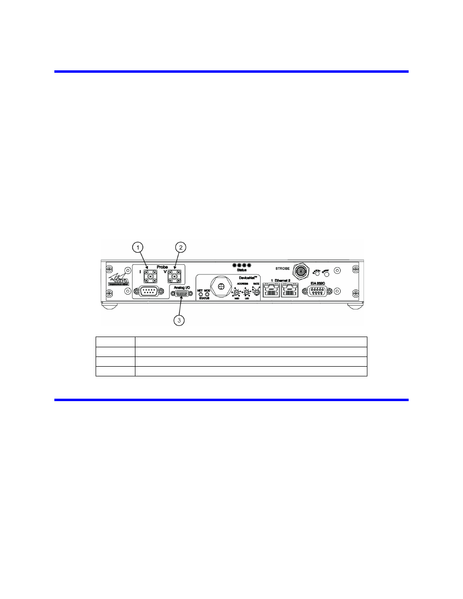
Connect the current and voltage data cables to the receiver (Figure on page 7).
Torque the SMA connectors to 1.55 Nm (±0.15 Nm).
5.
Connect the temperature / data cable to the receiver.
6.
Connect the external power supply (24 VDC) to the Power connector on the rear of
the receiver. Refer to Appendix 8
for pinout data for the DeviceNet connector.
7.
Apply power to the power supply and verify that the Power On LED on the receiver
lights.
8.
Verify communication with the host computer.
Figure 4 Receiver Cable Connections from Sensor
Installing the BDS Graphical User Interface Application
1.
Run “7001A242-X_BDSGUI_setup-X.exe”.
Note: This will create a short under the start menu folder “Start Bird->Bird
Technologies Group->BDS GUI.”
2.
Copy the shortcut onto the PC’s desktop (optional).
Item
Description
1
Current sensor connector
2
Voltage sensor connector
3
Sensor temperature / data connector (DB-9)