Figure 2 bds receiver mounting holes, Installing the sensor, Figure 3 sensor cable connections – Bird Technologies BDS-Manual User Manual
Page 20
6
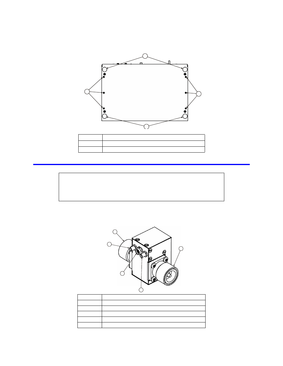
Figure 2 BDS Receiver Mounting Holes
Installing the Sensor
1.
Connect the sensor RF In connector to the feed side of the host RF source cable.
2.
Connect the sensor RF Out connector the load side of the host RF source cable.
Figure 3 Sensor Cable Connections
Item
Description
1
Mounting feet, rubber
2
Mounting holes, 6-32 threaded
CAUTION
Bending RF cables can cause damage. When routing RF cables, the minimum
bend radius is 2 inches (25.4 mm). Do not bend the cables more than the
minimum bend radius. Failure to comply may result in permanent damage to the
cable and reduced equipment performance.
1
1
2
2
Item
Description
1
RF output connector
2
RF input connector
3
Current connector, SMA standard polarity
4
Temperature / data connector, 7 pin
5
Voltage connector, SMA reverse polarity
1
2
5
3
4
Note: Standard BDS
sensor shown.
- SK-4000-TC-Manual (56 pages)
- SK-4000-TC-Datasheet (2 pages)
- SH-36S-Manual (206 pages)
- SH-36S-Datasheet (4 pages)
- SH-36S-PC-Manual (130 pages)
- SH-36S-PC-Datasheet (2 pages)
- SH-36S-PC-Quick Start (2 pages)
- SH-36S-RM-Datasheet (2 pages)
- SA-3600XT-Manual (112 pages)
- SA-3600XT-Datasheet (2 pages)
- AT-500-Manual (73 pages)
- AT-500-Datasheet (2 pages)
- AT-800-Manual (74 pages)
- 89-83F-02-03-Manual (2 pages)
- 89-83F-02-03-Datasheet (1 page)
- 8251 Series-Datasheet (1 page)
- 8251 Series-Manual (30 pages)
- DA10 VHF Series-Datasheet (2 pages)
- DA10 VHF Series-Manual (47 pages)
- 8865SC13-Datasheet (2 pages)
- 8865SC13-Manual (28 pages)
- 8890-300SC13-Manual (28 pages)
- 8921SC13-Manual (28 pages)
- 8931-115SC13-Manual (34 pages)
- BDS-Datasheet (2 pages)
- SCC7 Series-Datasheet (2 pages)
- SCC7 Series-Manual (45 pages)
- MSCC7 Series-Datasheet (2 pages)
- MSCC7 Series-Manual (35 pages)
- SCC8 Series-Datasheet (2 pages)
- SCC8 Series-Manual (47 pages)
- 4020 Series-Datasheet (1 page)
- 4020 Series-Manual (4 pages)
- 4027A Series-Datasheet (2 pages)
- 4027A Series-Manual (6 pages)
- 4027F Series-Datasheet (2 pages)
- 4027F Series-Manual (6 pages)
- 4028 Series-Datasheet (2 pages)
- 4028 Series-Manual (6 pages)
- 7022-Datasheet (4 pages)
- 7022-Manual (27 pages)
- ACM Series-Datasheet (2 pages)
- ACM Series-Manual (40 pages)
- BPME Series-Datasheet (4 pages)