Analog i/o, Figure 13 analog i/o dialog – Bird Technologies BDS-Manual User Manual
Page 42
28
Tolerance -
The Tolerance field defines the tracking filter window as a percentage from the center of the funda-
mental frequency. This gives the frequency range of a generator for a frequency.
Example - For a 2 MHz generator that moves from 1.8 to 2.2 MHz, you would enter a toler-
ance of at least 10%. The input value range for this field is 0.1 to 20%. The maximum toler-
ance for a frequency is limited based on the following formula: 5/frequency in MHz * 100.
Filter Width & Track Quality -
These are advanced parameters used to fine-tune the frequency tracking algorithm.
Note: It is recommended that these settings are kept at their default values of 0.1 and 0.01%, respectively.
Filter Width is used to widen or narrow the filters used to determine frequency lock.
Note: Filter Width ranges from 0.01 to 2.56%.
Note: Defaults for Filter Width: 0.1%.
Track Quality is used to adjust lock speed at the expense of accuracy. The higher the value, the lower the quality and
the lower the frequency accuracy.
Note: Track Quality ranges in value from 0.01 to 0.256%.
Note: Default for Track Quality: 0.01%.
Selected Frequencies -
Displays all frequencies that have been added to the measurement configuration. Fre-
quencies are listed in MHz. Column headers (from left to right):
•
Fundamental in MHz
•
Harmonic (overtone) number (0-15)
•
Intermod number (-3 to 3, 0 means no IMD)
•
Frequency in MHz.
Clicking on a fundamental in the list will highlight all frequencies for the fundamental.
Note: Harmonics or IMD frequencies can be clicked on individually.
Note: Clicking the “<< Remove” button will remove the highlighted frequencies from the list.
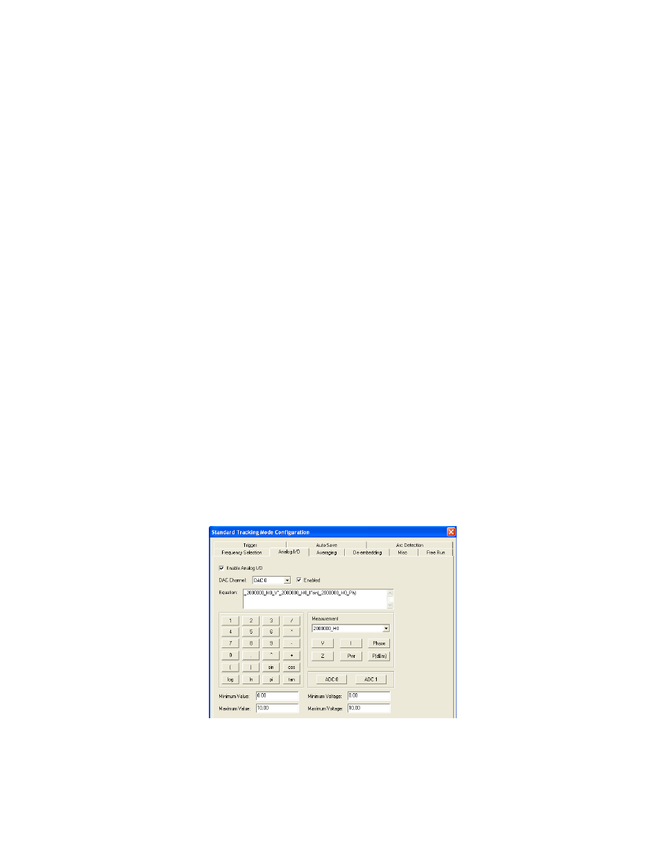
Analog I/O
The Analog I/O page provides options for configuring the DAC outputs and analog inputs.
Figure 13 Analog I/O Dialog