Averaging, Figure 14 averaging dialog – Bird Technologies BDS-Manual User Manual
Page 43
29
Analog I/O Spec -
:
•
Two analog inputs, 0 to 10V full-scale, 10K ohm input resistance.
Note: Can be assigned to any of the analog outputs or used for set-point or power threshold adjustment.
•
Five individual outputs, 0-10 V DC full-scale, 1000 Ohm source impedance.
•
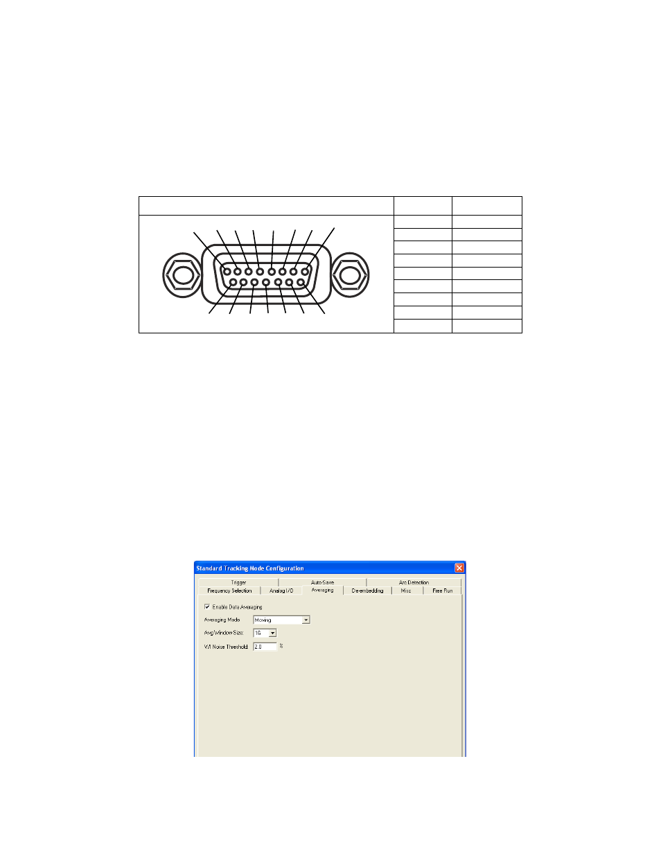
Analog I/O DB15 header pin descriptions:
Enable Analog I/O -
Enables/Disables analog I/O.
DAC Channel -
Selects the DAC channel to configure and enable. All settings listed on the page pertain to the
selected DAC. There are 5 DAC channels, labeled “DAC0” – “DAC4”.
Equation -
Allows a user to enter an equation that is processed by the receiver. The equation can be as basic as a
voltage output or as complex as the functions and controls allow. Measurement results can be included in the equa-
tion, as well as the readings from ADC0 & 1.
Note: The result of the equation is scaled according to the minimum and maximum value and voltage set-
tings. The DAC is programmed with the resulting voltage level.
Note: Update rate of the analog I/O is based on the measurement cfg (frequency selector). The DACs are
updated after a measurement set is available and the result of the equation is ready.
Averaging
The BDS offers two types of data averaging for Standard Tracking Mode: Simple (Fixed) or Moving. Both averaging
modes will reduce signal-to-noise ratio in a measurement. Averaging is performed in the receiver.
Figure 14 Averaging Dialog
Analog I/O Head
Pin
Description
Pin 1
ADC 1
Pin 2
ADC 0
Pin 3
GND
Pin 4
DAC 4
Pin 5
DAC 3
Pin 6
DAC 2
Pin 7
DAC 1
Pin 8
DAC 0
Pin 9 - 15
GND
1
2
3
4
5
6
7
8
9
10 11 12 13 14 15