Rockwell Automation 1394 SERCOS Interface Multi-Axis Motion Control System User Manual
Page 79
Publication 1394-IN024B-EN-P — February 2004
Interconnect Diagrams
A-15
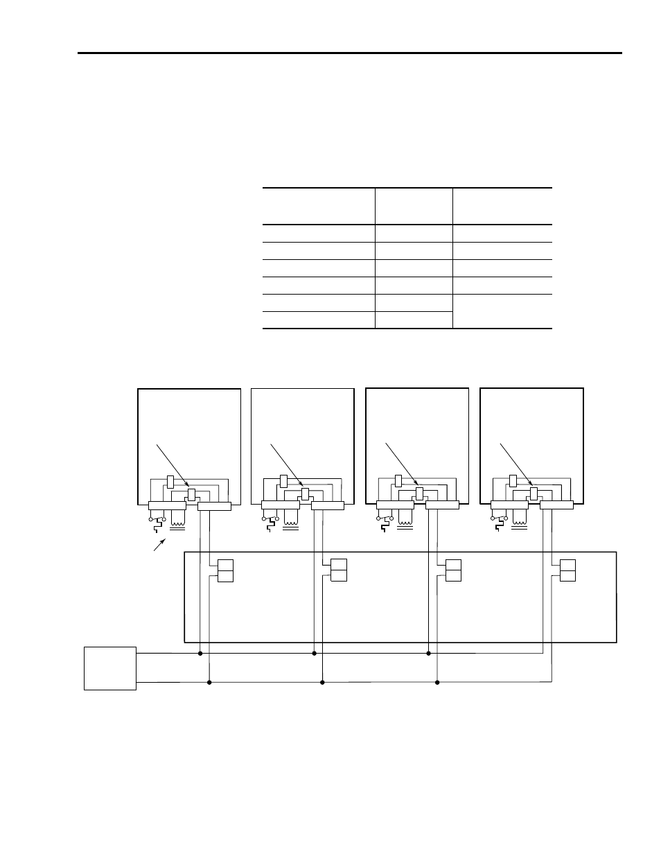
The example below shows 1394 series C axis modules with internal
brake filtering. Each axis is connected to a motor with a brake rated at
less than 1A. A separate pilot relay is not required. Motor brakes that
do not require a pilot relay are shown in the table below.
Note: Suppression devices and pilot relays impact motor brake
response time.
Figure A.13
Brake Interconnect Diagram
Note: Refer to Figure 1.3 for the location of the TB1/TB2 connectors
and pin-out diagram.
Note: Refer to figures 1.1 and 1.2 for the location of the 10-pin relay
output connector.
Motor Series:
Brake Option:
Brake Response Time
Pickup/Dropout
mSec
1326AB-B4
K4
120/20
1326AS-B3
K3
38/10
1326AS-B4
K4
44/13
MPL-B3 (460V)
4
50/20
MPL-B4 (460V)
4
110/25
MPL-B45 (460V)
4
9
10
24V DC
Power Supply
+ DC
DC com
Relay
Output 0
8
7
Relay
Output 1
6
5
Relay
Output 2
4
3
Relay
Output 3
1394 SERCOS Interface
Control Board
1394C-SJT
xx-D
Axis 0
TB1
Axis 2
Axis 3
Motor brake
filter (Series C)
TB2
1394C-AM
xx
TB1
TB2
1394C-AM
xx
1 2 3 4
Axis 1
TB1
TB2
1394C-AM
xx
TB1
TB2
1394C-AM
xx
1 2
3 4
Motor Brake
I <1A
I <1A
I <1A
I <1A
Brake current rated
less than 1.0A
Motor brake
filter (Series C)
Brake current rated
less than 1.0A
Motor brake
filter (Series C)
Brake current rated
less than 1.0A
Motor brake
filter (Series C)
Brake current rated
less than 1.0A
1 2
3 4
1 2
3 4
1 2
3 4
1 2 3 4
1 2 3 4
1 2 3 4
1 2
1 2
1 2
1 2