Axis module/motor interconnect diagrams – Rockwell Automation 1394 SERCOS Interface Multi-Axis Motion Control System User Manual
Page 70
Publication 1394-IN024B-EN-P — February 2004
A-6
Interconnect Diagrams
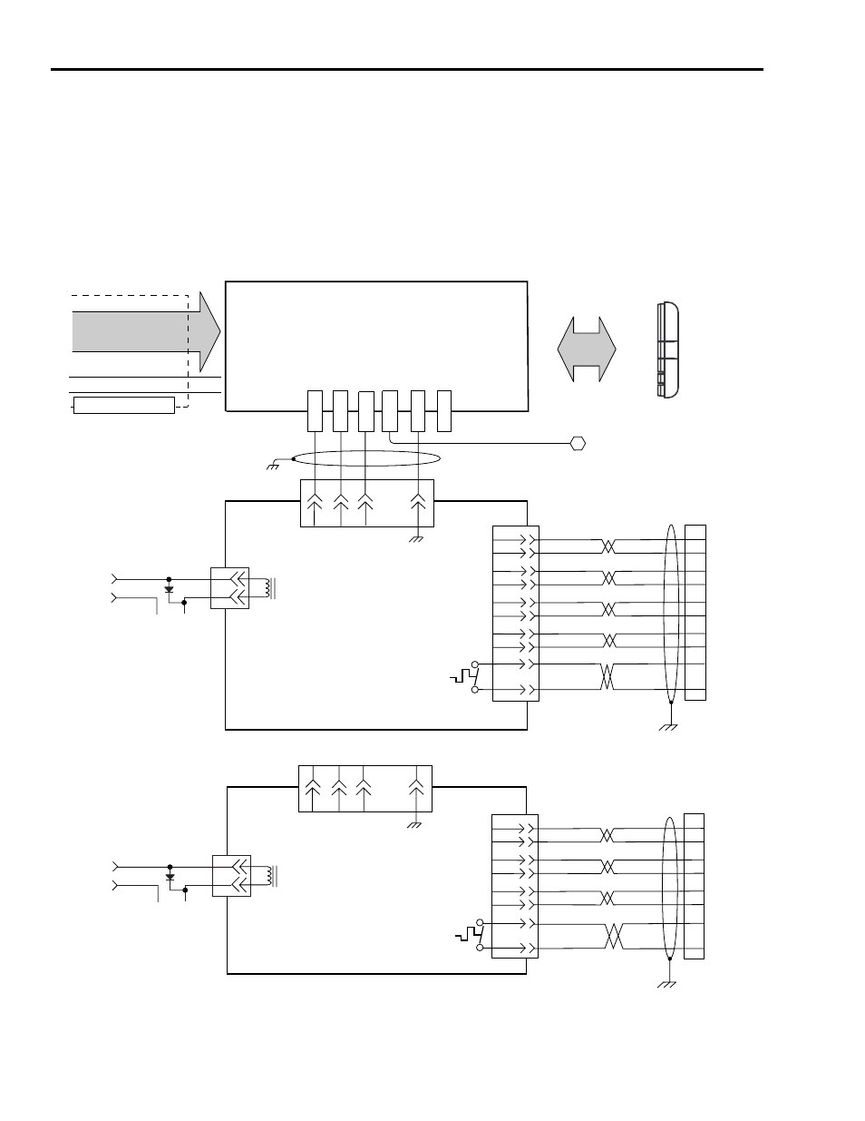
Axis Module/Motor
Interconnect Diagrams
This section contains the motor power, brake, and feedback signal
interconnect diagrams between an Axis Module and MP-Series,
1326AB, and 1326AS servo motors.
In the figure below, the 1394 axis module is shown connected to MP-
Series Low Inertia (460V) motors.
Figure A.6
Axis Module to MP-Series Low Inertia Motors Interconnect Diagram
4.0 mm
2
(12 AWG)
A
C
BR+
BR-
PE1
D
PE
PE2
PE3
U1
V1
W1
C
W
B
V
A
U
SIN+
SIN-
COS+
COS-
DATA+
DATA-
GREEN
WHT/GREEN
BLACK
WHT/BLACK
RED
WHT/RED
C
D
E
F
A
B
1
2
3
4
8
9
R
S
+9VDC
COM
ORANGE
WHT/ORANGE
N
P
6
5
A
C
BR+
BR-
D
PE
C
W
B
V
A
U
S2
S4
S1
S3
R1
R2
TS+
TS-
BLUE
WHT/BLUE
YELLOW
WHT/YELLOW
BLACK
WHT/BLACK
RED
WHT/RED
R
S
1
2
3
4
10
11
12
13
A
B
C
D
G
H
TS+
TS-
BLUE
WHT/BLUE
12
13
+24V
COM
Black
White
+24V
COM
Black
White
A
LOGIC POWER
& SIGNALS
DC BUS POS.
DC BUS NEG.
SLIDER INTERCONNECT
Motor Power Terminal Blocks
1394 AXIS MODULE
1394C-AMxx-xx
Axis Module
Cable Clamp
Note 6
2090-UXNBMP-18Sxx Brake Cable
Note 14
2090-XXNPMP-xxSxx or
2090-CDNBPMP-xxSxx
Motor Power Cable
Note 14
User-Supplied
+24V Power Supply
(1A max.)
Note 13
MPL-Bxxxx (460V)
SERVO MOTORS WITH
HIGH RESOLUTION FEEDBACK
2090-CDNFDMP-xxSxx Feedback Cable
Note 14
System Module
Cable Clamp
Note 6
Motor Feedback
Connector
(System Module)
Motor Feedback
Connector
(System Module)
To
System Module
Single Point
Bond Bar
TERMINATOR CONNECTED TO
LAST AXIS MODULE
SLIDER INTERCONNECT
TO ADDITIONAL AXIS MODULES
Three-Phase
Motor Power
Ground
Motor Feedback
Thermostat
Motor Brake
2090-UXNBMP-18Sxx Brake Cable
Note 14
User-Supplied
+24V Power Supply
(1A max.)
Note 13
MPL-Bxxxx (460V)
SERVO MOTORS WITH
RESOLVER FEEDBACK
2090-CDNFDMP-xxSxx Feedback Cable
Note 14
System Module
Cable Clamp
Note 6
Three-Phase
Motor Power
Ground
Motor Feedback
Thermostat
Motor Brake