Attention – Rockwell Automation 1394 SERCOS Interface Multi-Axis Motion Control System User Manual
Page 76
Publication 1394-IN024B-EN-P — February 2004
A-12
Interconnect Diagrams
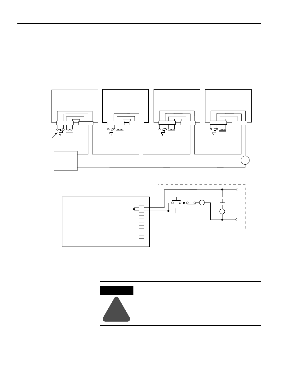
The example below shows 1394 (Series A and B) axis modules (no
internal brake or thermal switch filter). Separate 24V dc isolation
power supply and relay (CR2) are recommended. Using this start/stop
string configuration all axes are disabled when any one motor faults.
Figure A.11
Isolated Series Start/Stop String
1
120V ac (50/60 Hz) power may be used in place of 24V dc for motor thermal switch circuits in Series A and B axis
modules.
Note: Refer to Figure 1.3 for the location of the TB1/TB2 connectors
and pin-out diagram.
Drive System OK
Relay
1
2
3
4
5
6
7
8
9
10
+24V dc
24V dc com
CR2
24V AC/DC
or
120V AC,
50/60 HZ
STOP
START
CR1
CR1
CR1
M1
CR2
Axis 0
TB1
Axis 2
Axis 3
TB2
1394-AM
xx
TB2
Axis 1
TB1
TB2
TB1
TB2
1 2 3 4
1 2
3 4
3 4
3 4
3 4
3 4
1 2 3 4
1 2
1 2
3 4
3 4
1 2 3 4
1 2 3 4
1 2
3 4
TB1
1394-AM
xx
1394-AM
xx
1394-AM
xx
24V dc
Power Supply
1
Motor thermal switch wiring for
1326AB/AS motor resolver feedback
1394 SERCOS Interface
Control Board
1394C-SJTxx-D
Relay Output
Connector
Refer to Attention statement below
ATTENTION
!
Implementation of safety circuits and risk assessment
is the responsibility of the machine builder. Please
reference international standards EN1050 and EN954
estimation and safety performance categories. For
more information refer to Understanding the
Machinery Directive (publication SHB-900).