Rockwell Automation 1394 SERCOS Interface Multi-Axis Motion Control System User Manual
Page 13
Publication 1394-IN024B-EN-P — February 2004
Commissioning Your 1394 SERCOS Interface System
1-5
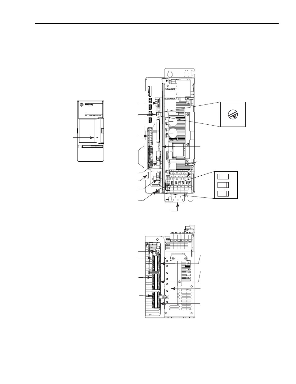
Use the figure below to locate the 1394C-SJT22-D System Module
connectors and indicators.
Figure 1.2
1394 System Modules (1394C-SJT22-D)
Note: Power, feedback, and I/O connectors are shown, however for
wiring information, refer to the 1394 SERCOS Interface
Installation Manual (publication 1394-IN002x-EN-P).
Enable0
Home0
Reg0_Com
Reg0_1
Pos_Otrav0
Neg_Otrav0
I/O_Com
Reg0_2
AXIS 0
Enable3
Home3
Reg3_Com
Reg3_1
Pos_Otrav3
Neg_Otrav3
I/O_Com
Reg3_2
AXIS 3
Enable2
Home2
Reg2_Com
Reg2_1
Pos_Otrav2
Neg_Otrav2
I/O_Com
Reg2_2
AXIS 2
Enable1
Home1
Reg1_Com
Reg1_1
Pos_Otrav1
Neg_Otrav1
I/O_Com
Reg1_2
AXIS 1
1
5
8
4
1 5
8
4
1
5
8
4
1
5
8
4
OUTPUT 0
OUTPUT 1
OUTPUT 2
OUTPUT 3
DRIVE SYSTEM OK
RELAY OUTPUTS
1
1394 Digital Servo Controller
System Module
SERCOS interface
TM
10
01
2
3
4 5 6
7
89
Status
DANGER
RISK OF ELECTRICAL SHOCK. HIGH VOLTAGE MAY
EXIST UP TO FIVE MINUTES AFTER REMOVING POWER.
SERCOS System Module
01
2
3
4 5 6 7
8
9
OFF ON
1 2 3
1 2 3
Analog Outputs
Connector
Relay Outputs
Connector
Discrete Input
Connectors (4)
SERCOS Base Node
Address Switch
Network Status LED
SERCOS Baud Rate
and Optical Power Switches
SERCOS Transmit (Tx) Connector
SERCOS Receive (Rx) Connector
DPI/SCANport Connector
System Module, front view
(1394C-SJT22-D is shown)
System Module, bottom view
(1394C-SJT22-D is shown)
Single Point
Bond Bar
Axis 0 Auxiliary Feedback
Axis 1 Motor Feedback
Terminal Block for Logic Power, Input Power,
and External Shunt Connections
Tie Down Anchor
System Module
Status LED
1394 System Module
Front Cover
Axis 3 Motor Feedback
(in four axis system) or
Axis 2 Auxiliary Feedback
(in three axis system)
Axis 1 Auxiliary Feedback
Axis 0 Motor Feedback
Cable Clamp Grounding Bracket
(one clamp installed)
Axis 2 Motor Feedback
(in four axis system) or
Axis 3 Auxiliary Feedback
(in two axis system)