Rockwell Automation 1394 SERCOS Interface Multi-Axis Motion Control System User Manual
Page 17
Publication 1394-IN024B-EN-P — February 2004
Commissioning Your 1394 SERCOS Interface System
1-9
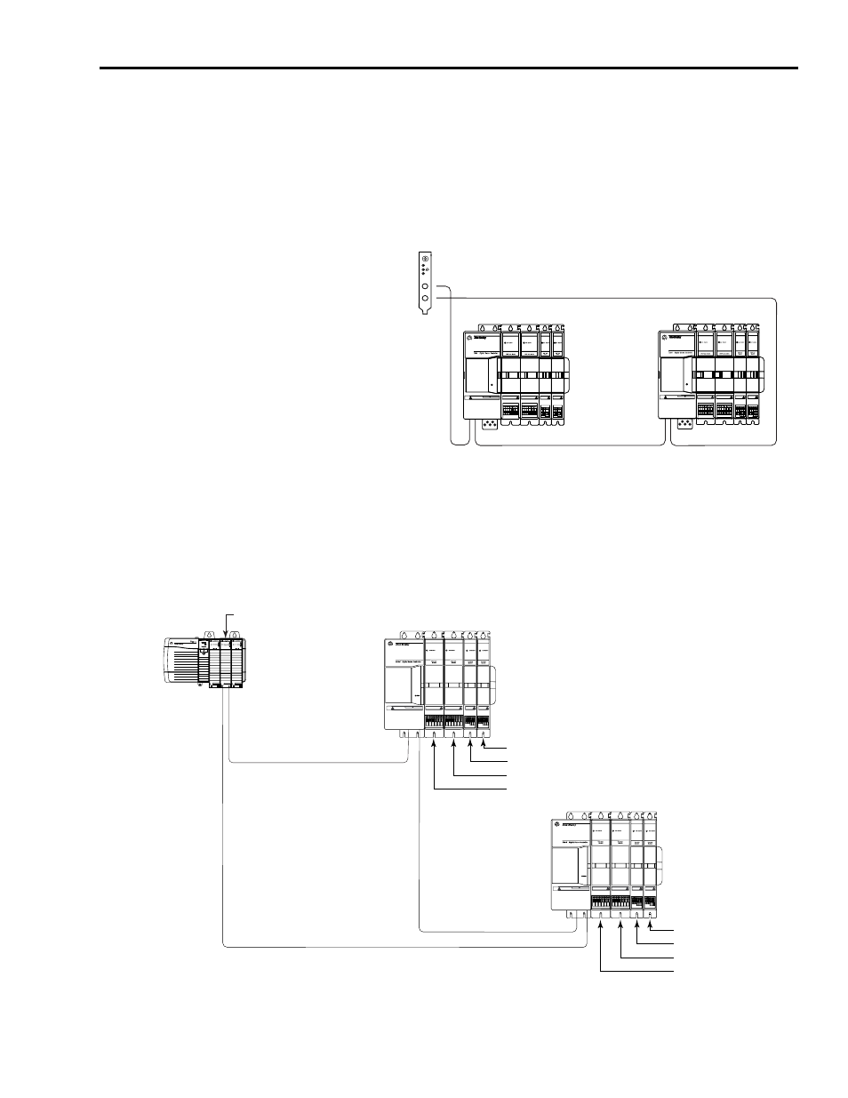
Refer to Figure 1.5 for an example of the fiber-optic ring connections
between the 1394 system module(s) and the SoftLogix PCI card.
Although Figure 1.5 only illustrates the SERCOS fiber-optic ring with
the SoftLogix PCI card, node addressing for SoftLogix is done the
same way as shown in the ControlLogix example.
Figure 1.5
Fiber-Optic Ring Connection (SoftLogix)
Axis 0 of each system module has a node address of the switch setting
times 10 (for example: system number 1 times 10 = 10 and axes 1-3 on
this system are numbered 11, 12, and 13, respectively). Refer to Figure
1.6 for an example of how node addresses are assigned.
Figure 1.6
Axis Module Node Addresses
0
8
4
C
67
5
3
2
1
9A
B
E
D
F
TX
RX
OK
CP
Status
DANGER
RISK OF ELECTRICAL SHOCK. HIGH VOLTAGE MAY
EXIST UP TO FIVE MINUTES AFTER REMOVING POWER.
SERCOS System Module
Status
DANGER
RISK OF ELECTRICAL SHOCK. HIGH VOLTAGE MAY
EXIST UP TO FIVE MINUTES AFTER REMOVING POWER.
SERCOS System Module
Receive
Transmit
SoftLogix
1784-PM16SE SERCOS
interface PCI Card
1394 SERCOS
interface System
Receive
Transmit
SERCOS fiber-optic ring
Transmit
1394 SERCOS
interface System
Receive
DANGER
RISK OF ELECTRICAL SHOCK. HIGH VOLTAGE MAY
EXIST UP TO FIVE MINUTES AFTER REMOVING POWER.
DANGER
RISK OF ELECTRICAL SHOCK. HIGH VOLTAGE MAY
EXIST UP TO FIVE MINUTES AFTER REMOVING POWER.
SERCOS System Module
SERCOS System Module
23
22
21
2x10=20
13
12
11
1x10=10
1394 SERCOS interface System
Number 1
1394 SERCOS interface System
Number 2
= Axis 3 node address
= Axis 2 node address
= Axis 1 node address
= Axis 0 node address
ControlLogix Chassis
SERCOS ring
SERCOS ring
SERCOS ring
1756-MxxSE SERCOS interface Module
= Axis 3 node address
= Axis 2 node address
= Axis 1 node address
= Axis 0 node address