Applying power to the 1394 sercos interface system – Rockwell Automation 1394 SERCOS Interface Multi-Axis Motion Control System User Manual
Page 28
Publication 1394-IN024B-EN-P — February 2004
1-20
Commissioning Your 1394 SERCOS Interface System
Applying Power to the 1394
SERCOS interface System
This procedure assumes that you have wired your 1394 SERCOS
interface system, your SERCOS interface module and verified the
wiring. To apply power to your 1394 system:
1. Apply 24V logic power to the system module and verify that the
logic power voltage at the input terminals of the system module is
24V AC (or 24V DC)
±
10%.
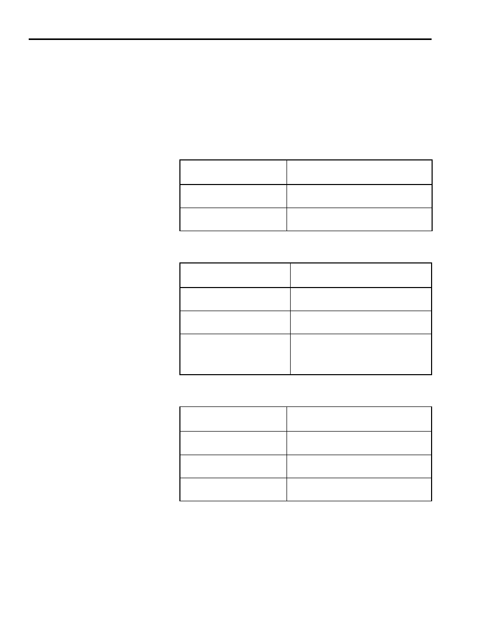
2. Observe the status LED on the system module.
3. Observe the three SERCOS LEDs on the SERCOS interface module.
4. Observe the network status LED on the system module.
If the system module
LED:
Do This:
Alternates red and green
System module ready.
Go to step 3.
Does not alternate red
and green
Go to the chapter Troubleshooting
Your 1394 SERCOS Interface System.
If the three SERCOS
LEDs:
Then:
Flash green and red
Establishing communication (wait
for steady green on all three LEDs).
Illuminates steady green
Communication ready.
Go to step 4.
Is not flashing or steady
green
Go to the appropriate Logix motion
module setup and configuration
manual for specific instructions and
troubleshooting.
If the network status
LED:
Then:
Flashes green
Establishing communication (wait
for steady green).
Illuminates steady green
Communication ready.
Go to step 5.
Is not flashing or steady
green
Go to the chapter Troubleshooting
Your 1394 SERCOS Interface System.