Locating sercos interface fiber-optic connectors, Configuring your 1394 sercos interface system – Rockwell Automation 1394 SERCOS Interface Multi-Axis Motion Control System User Manual
Page 15
Publication 1394-IN024B-EN-P — February 2004
Commissioning Your 1394 SERCOS Interface System
1-7
Locating SERCOS Interface
Fiber-Optic Connectors
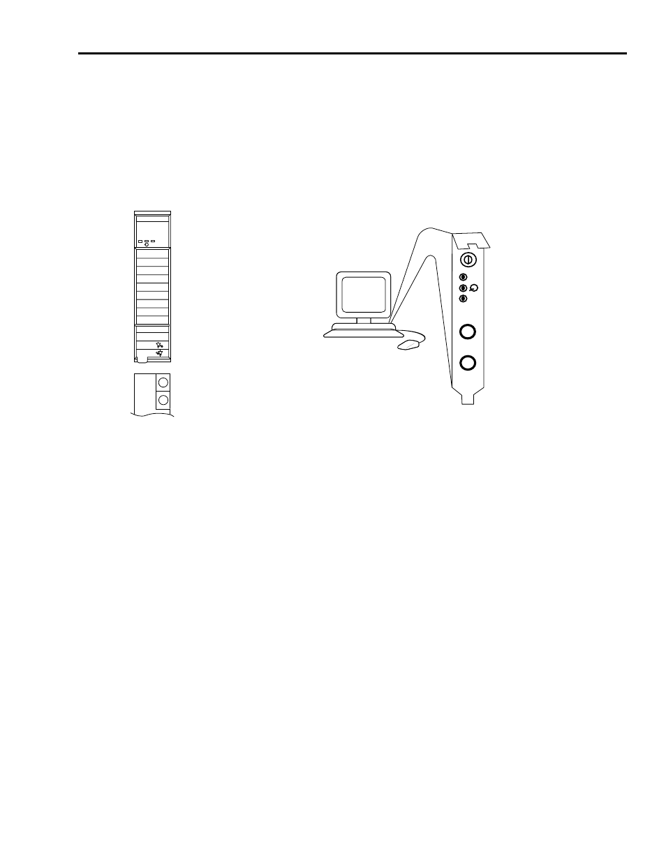
Use the figure below to locate the SERCOS interface fiber-optic
connectors. The fiber-optic ring is connected using the SERCOS
Receive and Transmit connectors.
Note: Plastic cable is available in lengths up to 32 m (105.0 ft). Glass
cable is available in lengths up to 200 m (656.7 ft).
Figure 1.4
ControlLogix and SoftLogix SERCOS Connector Locations
Configuring Your
1394 SERCOS interface
System
These procedures assume you have completed mounting, wiring, and
connecting your SERCOS interface module and 1394 SERCOS interface
drive as described in the 1394 SERCOS Interface Installation Manual
(publication 1394-IN002x-EN-P).
The procedures in this section apply to 1394 SERCOS interface drive
components and describe how to:
•
Configure your 1394 system module
•
Configure your Logix SERCOS interface module using RSLogix
5000 software
•
Download your program to your Logix controller
•
Apply power to your 1394 drive components
•
Test and tune your motor using RSLogix 5000 software
These procedures assume you have connected the fiber-optic cables
between your 1394 system module and the ControlLogix chassis with
1756-MxxSE interface module or personal computer with 1784-
PM16SE PCI card.
SERCOS interface
TM
Tx (rear)
Rx (front)
OK
CP
0
8
4
C
67
5
3
2
1
9A
B
E
D
F
TX
RX
OK
CP
ControlLogix
1756-M
xxSE SERCOS
interface Module
SERCOS
Receive Connector, Rx (front)
SERCOS
Transmit Connector, Tx (rear)
Front View
Bottom View
SERCOS Receive Connector, Rx
SERCOS Transmit Connector, Tx
SoftLogix
1784-PM16SE SERCOS interface PCI Card
(as viewed from the back of your PC)
RSLogix 5000