Attention, Figure 2.3 analog and relay output connectors – Rockwell Automation 1394 SERCOS Interface Multi-Axis Motion Control System User Manual
Page 56
Publication 1394-IN024B-EN-P — February 2004
2-20
Troubleshooting Your 1394 SERCOS Interface System
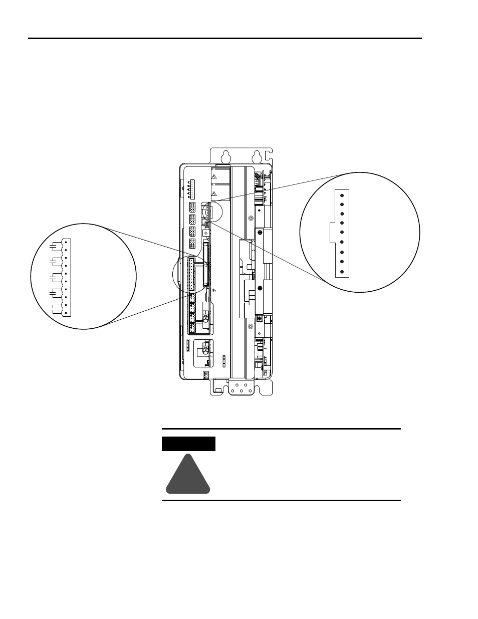
Using Analog Test Points to Monitor System Variables
There are four analog output test points accessible from the connector
on the front of the system module (refer to the figure below for the
connector location).
Figure 2.3
Analog and Relay Output Connectors
01
2
3
4 5 6
7
8
9
1 2 3
Analog_Out_1
Analog_Out_2
Analog_Out_3
Analog_Out_4
Common
N/C
N/C
N/C
N/C
DRIVE SYSTEM OK
OUTPUT 3
OUTPUT 2
OUTPUT 1
OUTPUT 0
1
10
1
9
Enable0
Home0
Reg0_Com
Reg0_1
Pos_Otrav0
Neg_Otrav0
I/O_Com
Reg0_2
AXIS 0
Enable3
Home3
Reg3_Com
Reg3_1
Pos_Otrav3
Neg_Otrav3
I/O_Com
Reg3_2
AXIS 3
Enable2
Home2
Reg2_Com
Reg2_1
Pos_Otrav2
Neg_Otrav2
I/O_Com
Reg2_2
AXIS 2
Enable1
Home1
Reg1_Com
Reg1_1
Pos_Otrav1
Neg_Otrav1
I/O_Com
Reg1_2
AXIS 1
1
5
8
4
1 5
8
4
1
5
8
4
1
5
8
4
OUTPUT 0
OUTPUT 1
OUTPUT 2
OUTPUT 3
DRIVE SYSTEM OK
RELAY OUTPUTS
1
DANGER
!
RISK OF ELECTRICAL SHOCK.
MORE THAN ONE
DISCONNECT SWITCH
MAY BE REQUIRED TO
DE-ENERGIZE THE
EQUIPMENT BEFORE
SERVICE.
ELECTRICAL SHOCK HAZARD
FROM ENERGY STROAGE
CAPACITORS.
VERIFY LOW VOLTAGE
DISCHARGE BEFORE
SERVICING.
SEE INSTRUCTIONAL MANUAL.
DANGER
!
1394 Digital Servo Controller
System Module
SERCOS interface
TM
10
- Control Reset
- SERCOS
Base Address
x10
- Analog_Out_1
- Analog_Out_2
- Analog_Out_3
- Analog_Out_4
- Common
- N/C
- N/C
- N/C
- N/C
AXIS 0
AXIS 1
AXIS 2
AXIS 3 RELA
Y
OUTPUTS
SERCOS
Network Status
- SERCOS
Receive
- SERCOS
Transmit
OFF ON
Analog Output Connector (9-pin)
Relay Output Connector (10-pin)
(Feedback and I/O connector kit
part number 1394C-CCK-D)
1394C-SJTxx-D
(5 and 10 kW)
See Attention statement
below.
ATTENTION
!
To avoid damage to the system, do not short
the unused pins (6-9) on the Analog Output
connector (shown above) together or to
ground.