Motors, Power connections, 0rwruv – Rockwell Automation 1398-PDM-xxx ULTRA Plus Series Positioning Drive Module User Manual
Page 82: 3rzhu &rqqhfwlrqv
Publication 1398-5.1 — January 2000
3-18 Wire the ULTRA Plus PDM Components
Motors
Power Connections
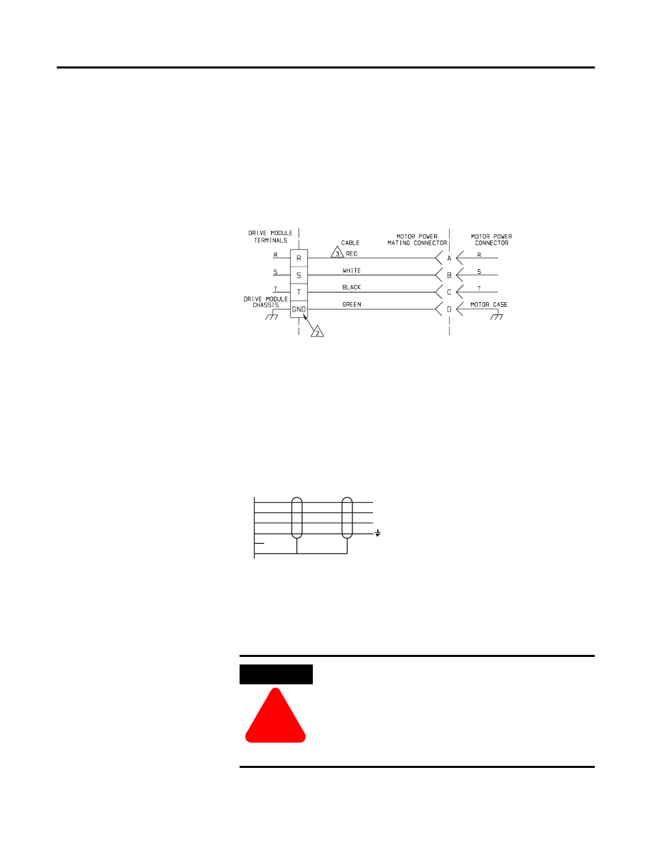
3KDVLQJ RI WKH WKUHHSKDVH GULYH PRGXOH RXWSXWV 5 6 DQG 7 PXVW FRQIRUP WR
WKH PRWRU 5 6 DQG 7 OHDGV IRU SURSHU RSHUDWLRQ &RQQHFW WKH HDUWK JURXQG WR
HQVXUH D VDIH LQVWDOODWLRQ DQG SURSHU RSHUDWLRQ 6HH )LJXUH IRU FRQQHFWRU
SLQ DQG VLJQDO LGHQWLILFDWLRQ RI + DQG )6HULHV PRWRUV
Figure 3.13
Motor power connections for H, and F-Series motors
6HH )LJXUH RQ SDJH IRU FRQQHFWRU SLQ DQG VLJQDO LGHQWLILFDWLRQ RI
16HULHV PRWRUV
Figure 3.14 Motor power connections N-Series motors
ATTENTION
!
+LJK YROWDJH PD\ EH SUHVHQW RQ WHUPLQDOV RI WKH 8/75$
3OXV 3'0
5HPRYH SRZHU DQG GLVFRQQHFW WKH SRZHU FDEOH EHIRUH
PDNLQJ RU UHPRYLQJ DQ\ FRQQHFWLRQ
)DLOXUH WR REVHUYH WKLV SUHFDXWLRQ FRXOG UHVXOW LQ GDPDJH WR
WKH HTXLSPHQW RU VHYHUH ERGLO\ LQMXU\
1. Do not interchange any connection in the cable
2. Ground connections:
1398-PDM-10, 20, 30, 75, and 150B – screw terminal
1398-PDM-25, 50, 100, and 150 – M6 stud
3. Wire colors shown reflect cables supplied by Rockwell Automation/
Allen-Bradley
E
N/C
D
B
C
A
BROWN
BLACK
BLUE
GRN/YEL
SHIELD
S
T
R
1. Do not interchange any connection in the cable
2. Ground connections:
1398-PDM-10, 20, 30, 75, and 150B – screw terminal
1398-PDM-25, 50, 100, and 150 – M6 stud
3. Wire colors shown reflect cables supplied by Rockwell Automation/
Allen-Bradley