Understanding feedback and i/o cable connections, Motor feedback connector pin-outs, Motor feedback connector pin-outs -26 – Rockwell Automation 1394 SERCOS Interface Multi-Axis Motion Control System Installation Manual User Manual
Page 80
Publication 1394-IN002B-EN-P — February 2004
3-26
Connecting Your 1394 SERCOS Interface System
Understanding Feedback
and I/O Cable Connections
The procedure in this section assumes that your 1394 system and axis
modules are already mounted and your power is wired. In this section
you will:
•
Prepare the feedback and I/O cables for wiring to connector
housings.
•
Make the connections and plug the housings into mating
connectors on the bottom of the 1394 system module.
•
Attach the feedback cable clamp to the feedback cable shield.
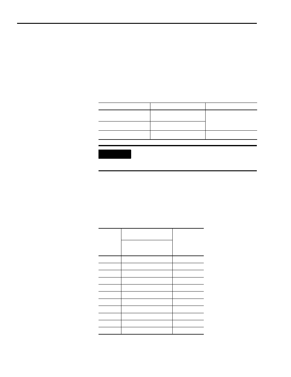
Motor Feedback Connector Pin-outs
The following table provides the signal descriptions and pin-outs for
the motor feedback (13-pin) connector to MP-Series and 1326AB
(M2L/S2L) motors.
For this motor series:
Using this type of feedback:
Use this feedback cable:
MP-Series (low inertia) or
1326AB (M2L/S2L)
High-resolution encoder
2090-CDNFDMP-Sxx
MP-Series
Motor resolver
1326AB/AS
Motor resolver
1326-CCUx-xxx
IMPORTANT
To improve the bond between the feedback cable
shield and the system module chassis ground, cable
shield clamps are included with system modules.
Motor
Connector
Pin
High Resolution Feedback
Signals for:
System Module
Connector Pin
MPL-Bxxx-M/-S and
1326AB-Bxxx-M2L/-S2L
460V Motors
A
Sine+
1
B
Sine-
2
C
Cos+
3
D
Cos-
4
E
Data+
8
F
Data-
9
N
EPWR_9V
6
P
ECOM
5
R
TS+
12
S
TS-
13
Shield
Shield
Shield Clamp