External shunt modules – Rockwell Automation 1394 SERCOS Interface Multi-Axis Motion Control System Installation Manual User Manual
Page 26
Publication 1394-IN002B-EN-P — February 2004
1-16
Installing Your 1394 SERCOS Interface System
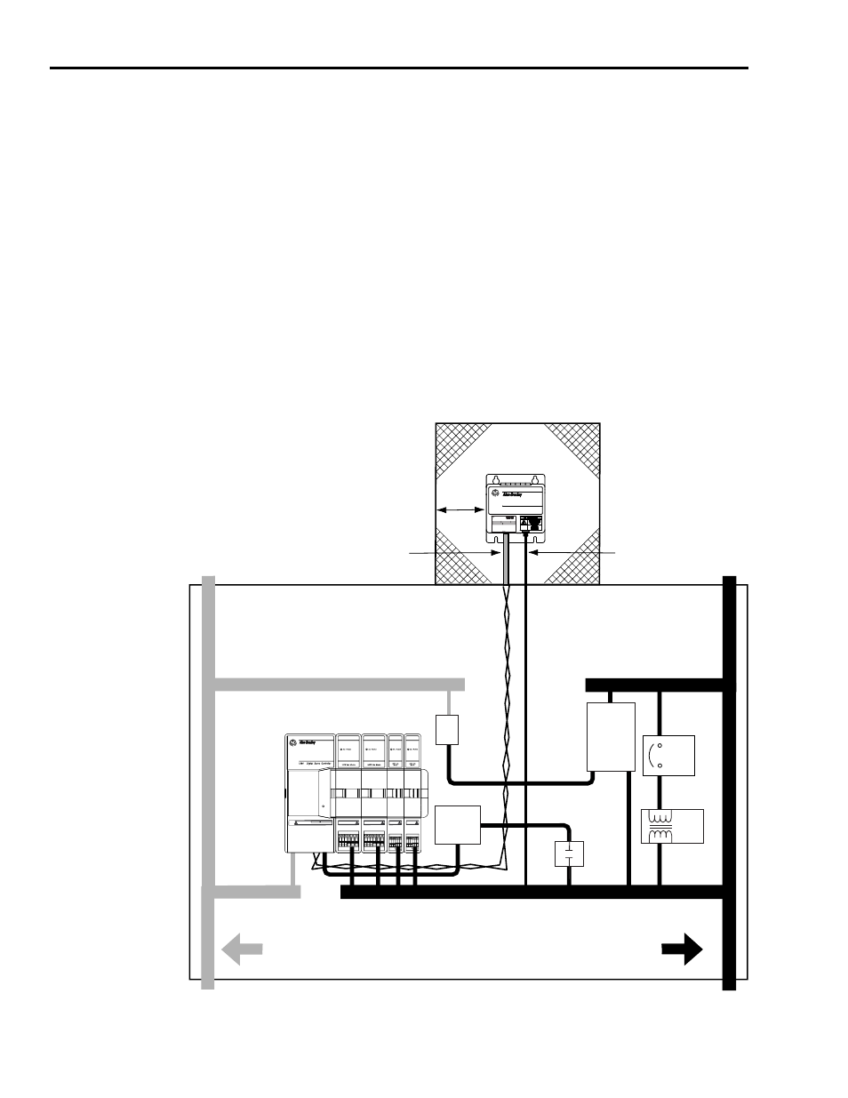
External Shunt Modules
Observe the following guidelines when mounting your external shunt
module (refer to Figure 1.9 and for an example).
•
Mount circuit components and wiring in the very dirty zone or in
an external shielded enclosure. Run shunt power and fan wiring
inside metal conduit to minimize the effects of EMI and RFI.
•
Mount resistors (other than metal-clad) in a shielded and
ventilated enclosure outside the cabinet.
•
Keep unshielded wiring as short as possible. Keep shunt wiring as
flat to the cabinet as possible.
•
Route thermal switch and fan wires separate from shunt power.
Figure 1.9
External Shunt Module Outside the Enclosure
C
C
D
D
VD
D
C
1394 Digital Servo Controller
300W Shunt Module
BULLETIN 1394 300W SHUNT MODULE
ALLEN-BRADLEY
FOR USE WITH 1394-SJT22-X SYSTEM MODULE
CAT.
PART
SER.
INPUT DC
INPUT AC
FOR FUSE REPLACEMENT USE:
BUSSMAN CAT. NO.
R
VD
Status
DANGER
RISK OF ELECTRICAL SHOCK. HIGH VOLTAGE MAY
EXIST UP TO FIVE MINUTES AFTER REMOVING POWER.
SERCOS System Module
(1)
Dirty Wireway
Clean Wireway
Customer-supplied
metal enclosure
150 mm (6.0 in.) of
clearance on all sides
of the shunt module
(minimum)
Enclosure
Shunt Power Wiring Methods:
Twisted pair in conduit (1st choice)
Shielded twisted pair (2nd choice)
Twisted pair, 2 twists per foot min. (3rd choice)
Metal conduit
(where required
by local code)
Route 24V dc I/O
Shielded Cable
Route Encoder/Analog/Registration
Shielded Cable
Very dirty shunt connections
segregated (not in wireway)
24V Motor
Brake PS
Circuit
Breaker
XFMR
AC
Line Filter
DC
Filter
Contactors
1394 SERCOS interface System
I/O and
Feedback Cables
Enclosure
Shunt thermal switch and
fan wires (when exist)